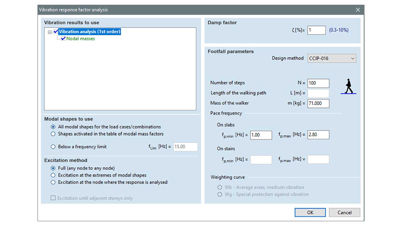
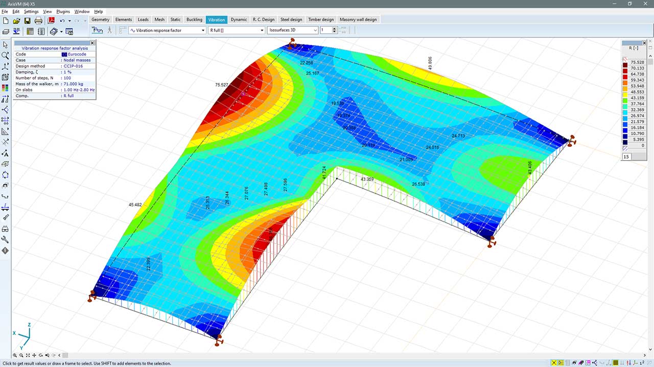
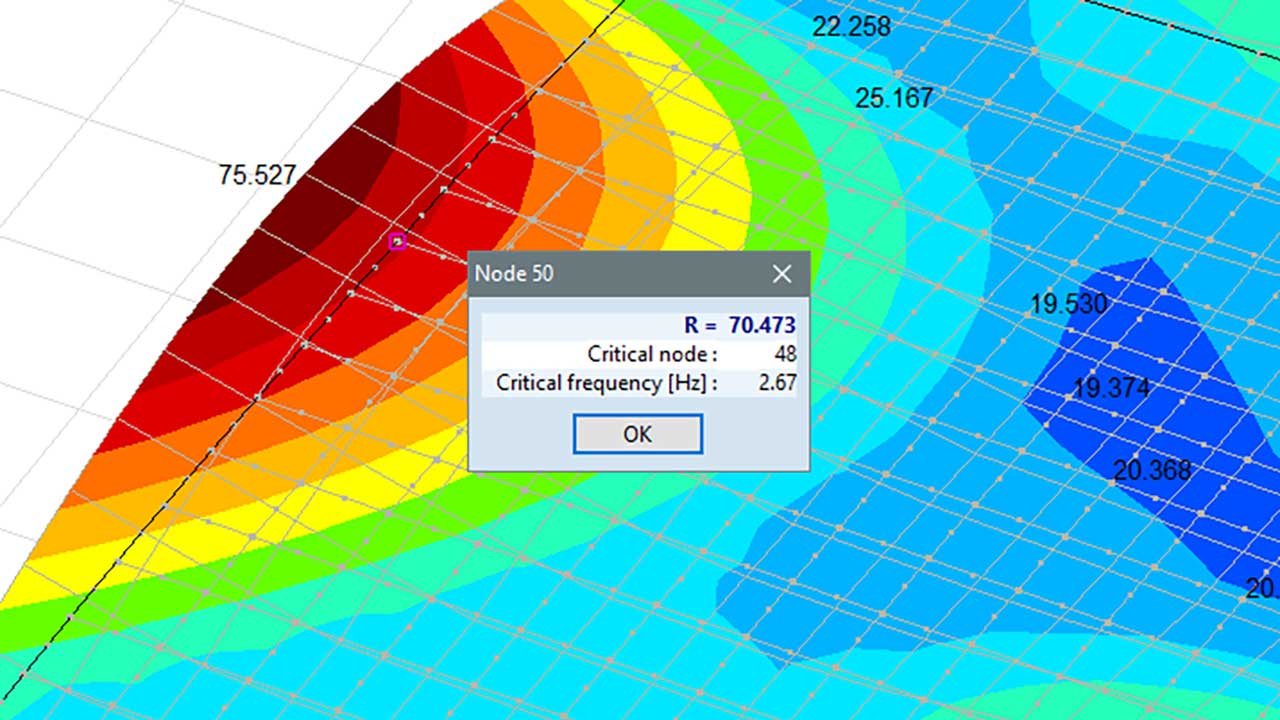
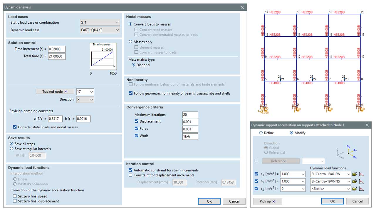
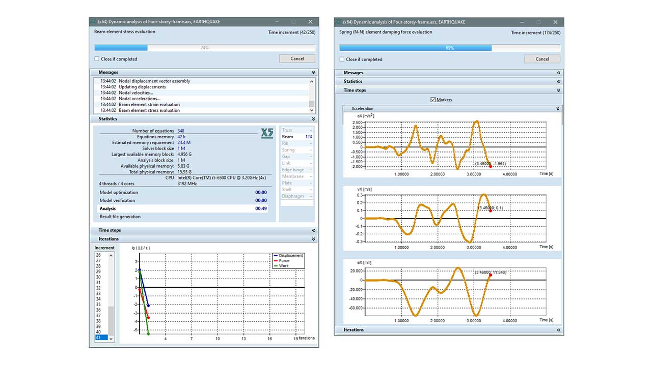
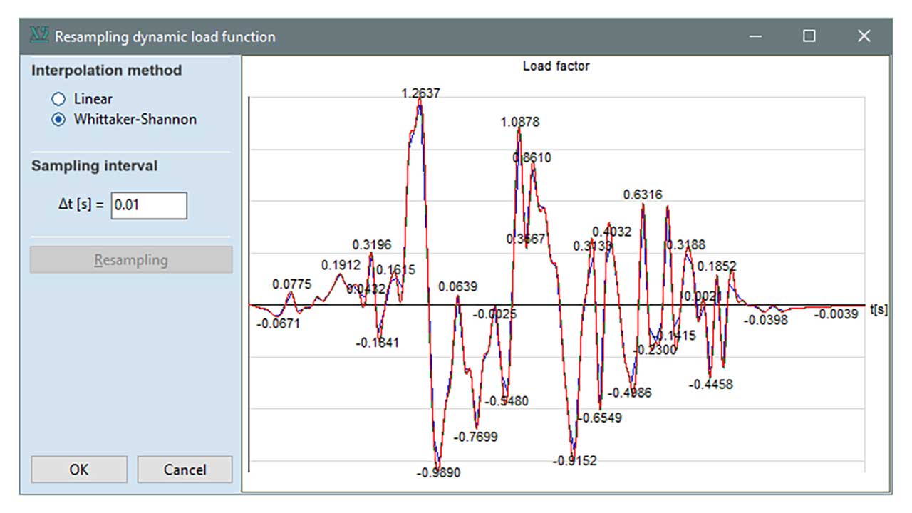
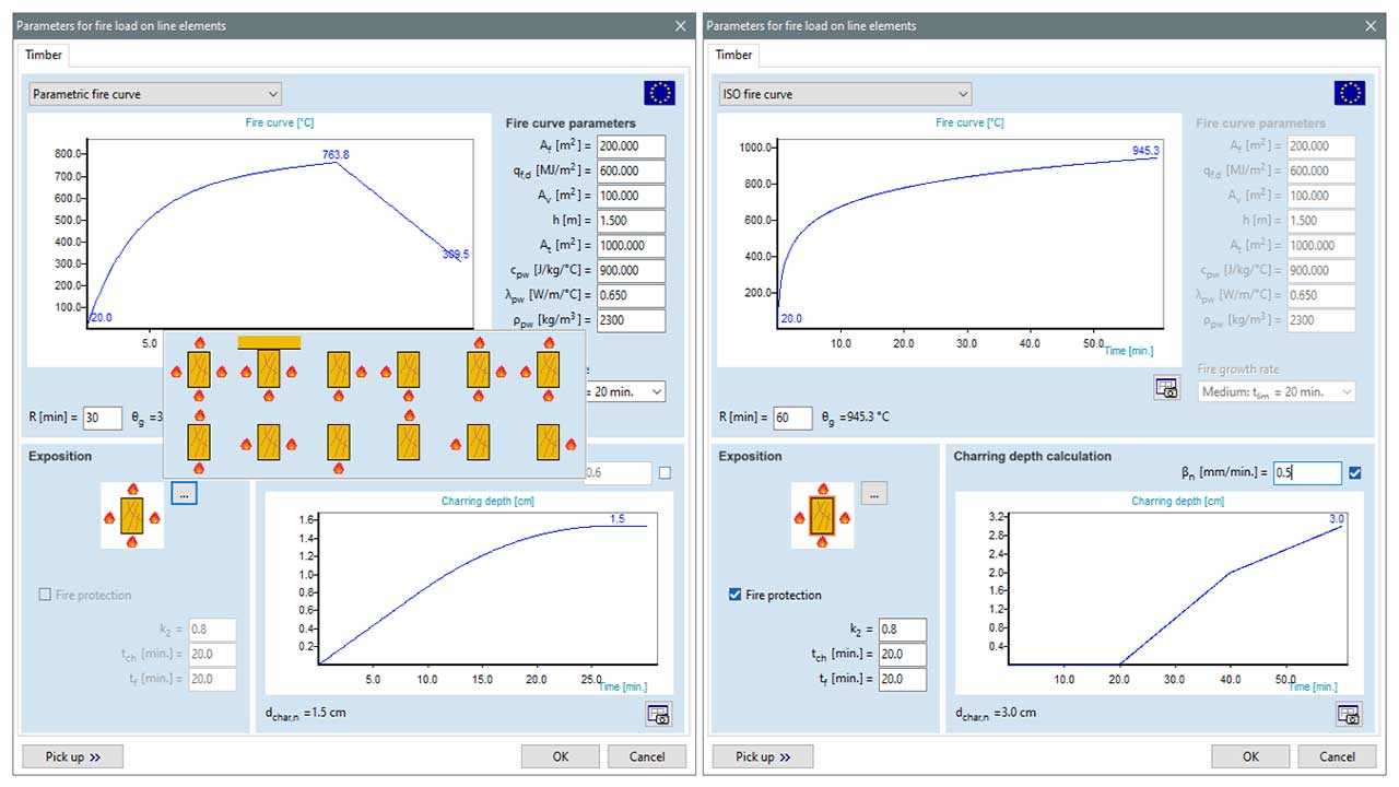
DYNAMIC ANALYSES

Dynamic modeling in structural analysis has become increasingly relevant as standards have become more and more rigorous in the subject. Furthermore, the extensive use of economical, lightweight buildings requires increasingly accurate dynamical analysis. These topics are addressed by the dynamic and footfall modules in AXISVM.

DYN MODULE

General dynamic analyses

FFA MODULE

Calculation of vibration respone factor for slabs

The module provides the ability to generate the snow and wind load on typical structures according to the standard automatically. It operates with the load panel tool of the software that must cover the affected outer contour planes of the structure since the automatically generated meteorological load can only be placed on these panels. The automatic critical load combination result can be applied efficiently to handle a significant number of possible load combinations.
In many cases, the simple schemes and design rules detailed in the standards are not applicable for the analysis of more complex structures. In the case of wind loads, it may be justified to carry out computational simulations and/or experiments to define the steady-state wind pressure for the structure.
The WIND module of the AxisVM software offers support to designers for such cases by wind load determination using digital wind tunnel simulation for arbitrary structures. A detailed description of the WIND module can be found on the Generation of meteorological loads page.
Requirements / recommendations

no requirements

DESIGN CODES

The DYN module is independent from design codes/standards.

CHARACTERISTICS

  • the time integration is carried out by the Newmark-beta implicit numerical method
  • geometric and material nonlinearity can be taken into account
  • the dynamic load functions can be defined by either numerical data at sampling points, or by analytical functions
  • the intermediate points of the load function can be determined with linear or Whittaker-Shannon interpolation
  • the accelerograms can be corrected in order to obtain zero end speed and displacement
  • the internal forces can be used in standardized design procedures, with caution

DETAILS

THE PARAMETERS OF DYNAMIC ANALYSIS

In the dynamic analysis, a static and a dynamic load case can be considered. The results are stored at every time step, or at specified time steps. In addition, the correction of the load function and interpolation method, as well as the nonlinearity and convergence criteria, can be set.

RUN-TIME MONITORING

The movement (displacement, velocity, acceleration) about a nodal degree of freedom can be monitored during analysis, which can reveal certain structural behavior during the analysis.

THE INTERPOLATION OF LOAD FUNCTIONS

If the sampling points of the load function are not coinciding with the time steps, the program interpolates the function value at a given instance of time with linear interpolation or with the Whittaker-Shannon formula. The latter can approximate a continuous function, which is better discretised with uniform time steps.

THE CORRECTION OF EARTHQUAKE ACCELEROGRAMS

The real (recorded) accelerograms can be modified. Due to measurement error, the recorded acceleration data does not result in zero end speed. The applied algorithm modifies the original acceleration in order to obtain zero end velocity and displacement.


DAMPING

The structural damping is taken into account using proportional, Rayleigh-damping. Nodal damping can be taken into account with spring and dashpot elements. Bilinear characteristic can be considered according to the Maxwell or Kelvin model.

PRESENTATION OF THE RESULTS

The computed kinematic results (displacements, velocities, accelerations) and internal forces and moments can be presented (plotted) as a function of time or as a function of any other time-dependent result.

ANIMATION

Animations can be displayed for time-dependent changes of any result component and can be saved as a GIF or AVI file type. The speed of replay can be adjusted and arbitrary subdomains can be chosen for the animation.

Nowadays, the cost-efficiency and ease of assembly of buildings and bridges have become more important. A possible consequence of this is a considerable decrease in structural weight. However, the dynamic effect of moving masses is typically larger on lightweight buildings. As a result, the buildings’ serviceability can be significantly restricted, due to disconcertingly large accelerations. In order to restrain the large accelerations, it is inevitable to control the vibrational serviceability limit state, for which the footfall analysis is a modern approach. A corresponding procedure has been implemented into the AxisVM software.

Further information: Footfall Analysis Guide >>

Requirements / recommendations

a basic package with surface elements is required (e.g. L3S, NL3P)

DESIGN CODES

The FFA module is independent from design codes/standards.

CHARACTERISTICS

  • the following two recommendations are built into the software:
  • Willford, M.R., Young, P. A Design Guide for Footfall Induced Vibration of Structures, Concrete Society, 2006
  • Smith, A. L., Hicks, S. J., Devine, P. J. Design of Floors for Vibration: A New Approach, The Steel Construction Institute, Ascot, 2009
  • the analysis can only be performed on floors (the angle between the domain’s normal vector and the direction of gravitation is less than 10°), and stairs (the angle between the domain’s normal vector and the vertical direction is between 10°-70°)
  • only linearly elastic structures can be considered
  • before the calculation, a vibration analysis must be performed
  • the footfall load excites only the nodes of surface elements; the nodes of line elements are not considered in the procedure
  • the method does not consider the horizontal component of the footfall load, which can have significant effect on the vibration of bridges. Therefore, the process is only capable of handling the vibration of buildings’ floors and stairs

DETAILS

PARAMETERS OF FOOTFALL ANALYSIS

The analysis can be adjusted with different parameters, depending on the nature of the problem. The user can select the modes, type of excitation, damping ratio, and the footfall parameters.

VIBRATION TYPES

In the case of footfall induced vibrations, the response of the system consists of two parts, namely: the transient part and the steady-state part. Fundamentally, the characteristic shape of the vibration can be one of these two types. For the most part, the stiffness of the structure and the duration of the excitation determine which type of vibration is dominant.

The user can choose between these two recommendations:

  • CCIP-016
  • SCI P354

"R" RESPONSE FACTOR RESULT COMPONENT

The vibration response factor result shows the envelope function of the response factor due to human induced vibration. The response factor is proportional to the maximum of the structural acceleration, thus the user can find the location and value of the largest acceleration.

NODAL RESULTS

Once the results are available, the user can obtain the response factor, the location of the critical excitation (index of the node) and the critical frequency for each node.

DOCUMENTATION

Documentation of the detailed calculations can be requested for the design results and can be included in the project report. The “Utilization in fire” table summarizes the fire design results, which helps communicate with fire safety engineers.