CUSTOMER PROJECTS
LAKE TISZA BIKE BRIDGES
LAKE TISZA, HUNGARY
Bridge Designer:
Structural Designer:
Year of Construction:
PROJECT DESCRIPTION
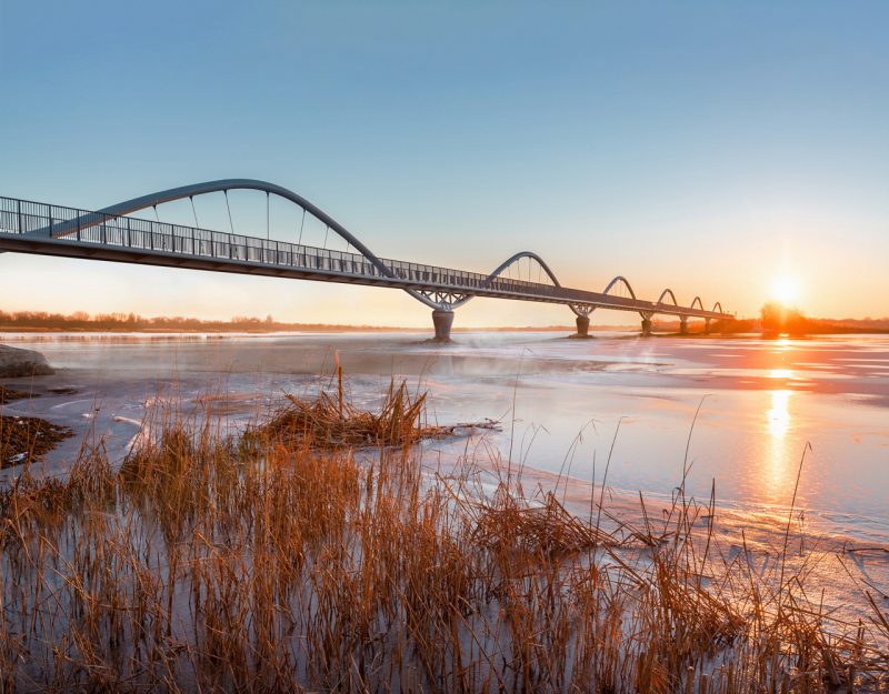
The cycling bridges of Lake Tisza are located on the route between Poroszló and Tiszafüred – by bridging the interconnected water surfaces of the reservoir, they provide a bicycle traffic connection independent of the public road through the basins of the lake and the Tisza River. The construction of the structures made it possible to safely cycle around the lake separated from traffic by closing a 65 km long bike path.
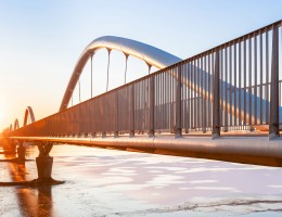
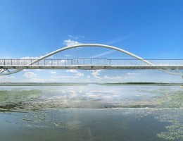
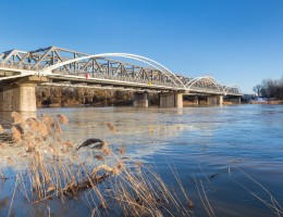
During the design of the bridges, great emphasis was placed on aesthetics and fitting in with the natural environment. The continuous arch bridges form a sine wave, fitting a formal element into the environment that can also be interpreted as a symbol of the national park. With SPECIÁLTERV’s two decades of expertise, the application of modern design technologies – including AXISVM – and the knowledge of the specifics of the design area, the amount of raw materials used for construction could be reduced by orders of magnitude, and structures could be built that minimized the disturbance of protected habitats. After the construction of the project, the number of cyclists increased substantially.
Following several domestic recognitions (MAGÉSZ, KTE, FIABCI), the bridges and the related infrastructure won the Silver Award of the international FIABCI World Prix d’Excellence in the Public Infrastructure/ Amenities. category in June.
The short film of the bridges can be viewed at this link, and the publication about the design can be found here.
Lake Tisza bridges – SPECIÁLTERV
SUPPORT STRUCTURE
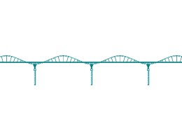
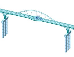
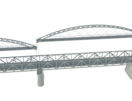
The structure of the Eger Bridge is an eight-span semi-intergral girder bridge, formed with an orthotropic steel box girder deck with a support distribution of 8.45 m + 50.72 m + 4 × 47.43 m + 50.72 m + 8.45 m, and a continuous tubular steel arch.
The total length of the superstructure is 308.46 m.
The Szomorka Bridge is a three-span semi-intergral girder bridge with a similar structure as the Eger Bridge. Support distribution is 19.25 m + 47.40 m + 19.25 m and the total length of the superstructure is 86.30 m.
The bicycle bridge over the Tisza River uses the stone-covered concrete pillars of the existing road bridge and rests on the reinforced concrete extension brackets of the existing pillar caps. As the end supports of the new bridge, new reinforced concrete abutments were being made next to the abutments of the road bridge. The superstructure system of the new bicycle bridge is simple-supported deck type truss structures in the outer spans, and a series of steel network arch bridges in the three intermediate bays. The spans of the bridge’s supports are: 34.11 + 3 × 68.50 + 34.10 m, the length of the superstructure is 279.47 m, the width of the entire superstructure is 3.312 m, the free width of the cycle road is 2.00 m.
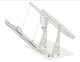
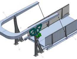
The fourth bridge is a single-span orthotropic steel openable girder bridge installed on an existing hydraulic structure of Channel No. X. It is the first openable cycle bridge in Hungary. It was a requirement for the bridge to be openable due to hydraulic requirements. To achieve this, we decided on choosing of the most economical solutions to span the opening of only 5.70 m. In the case of swing-arm drawbridges, also known as the “Dutch-type” drawbridges, the opening and closing is ensured by an external counterweight.
The movement takes place around the hinges located at the abutment on the Tiszafüred side. The bridge can be opened by a steel lifting structure resting on columns, with a reinforced concrete counterweight on the opposite side – making it possible for the cycle bridge to be opened by human force. The main span of the bridge is only 6.30 m, the bridge deck is 2.80 m wide.
STRUCTURAL DESIGN WITH AXISVM
In the case of the Eger and Szomorka Bridges, it was necessary to apply custom solutions when designing the connection between the superstructure and the substructure. These lengthy, straight structures rest on pipe girders, therefore we had to provide the supports with a rigid, torque-resistant grip in all directions (Mx, My, Mz), therefore we could not apply classic bearing structures and bearing arrangement solutions. The arch girders are supported on the pillars by a longitudinal and transverse torque-resistant connection. The stiffened tie down assembly provides fixed support with studs embedded in the pillar heads. The superstructure of Eger Bridge is fixed on the middle 3 pillars, on the outer 2 pillars on each side is ensured by a Teflon layer placed in the tie down assembly.
The superstructure supports of Szomorka Bridge are fixed on both intermediate pillars.
The thermal movements develop evenly towards the two abutments in case of both structures.
At each of the abutments, vertical support is provided by 2 pendulum columns. The pendulum columns allow longitudinal movement of the bridge due to thermal expansion, and they transmit the vertical force to the abutment. The transverse movement of the bridge ends is prevented by shearing pins attached to the knee walls of the abutments – a tube-in-tube system, without obstructing the thermal expansion movements.
The bridge, which is braced with a continuous multi-support, waving arch, is rigidly supported at the intermediate supports and articulated at the abutments.
Due to the weak subsoil, at the intermediate supports m3 piles per each support were required. The piles were arranged in a row, as this reduced the lower clamping rigidity of the “frame columns”, thereby reducing the effects of tensing in the rigid structure. The geometry of the pillars follows not only aesthetics, but also static aspects. The goal was a design that follows the stress, through which the rigidness of the pillar was gradually reduced as we moved towards the pile clamper.
As the structure is clamped in the subsoil with the piles and the clamping rigidity of the soil has an effect on the stresses of the superstructure, we examined the embedding rigidity of the piles over a wider range, in several different cases. The piles were modeled by limit spring embedding.
In the case of the Eger creek, the fixed grip on the intermediate 3 pillars proved to be adequate based on the results performed by as it was mentioned above. When designing the arc, the shape evoking the sine wave was a conceptual decision. Its rate and optimal geometry have been modified and tuned several times during the design phases, to meet the strict criteria of static, aesthetic, and manufacturability at the same time.
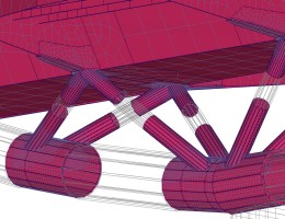
In the case of the grid bars connected to the arch girder, it is also the result of an aesthetic objective that the nodes did not receive external stiffening plates. The rod connections are slightly eccentric with respect to the arc girder axis; thus, the forces of the structure became more favorable for torsion. At the more used grid mbar connections, internal stiffening ribs were placed in the curved main support tube.
The webs of the cross girders are without a flange at the bottom, which is why the compliance of the cross girders to dent stability loss were examined in detail.
Only in the case of widened crossbars at the resting places, the cross girders had to be fitted with flanges and only on a short section.
Mainly to improve the dynamic behavior of the bridge structure, the sections of the arches under the tie girders were designed with concrete filling. The rods hanging the tie girder to the arches are arranged radially, their diameter increase continuously from the shoulder of the arch inwards, according to the stresses.
In case of the Tisza bridge, the arc height of the arch bridge is flat f/ = ~0.12, but due to the advantage of network system bridges, the arch does not get as much bending as in the case of arch bridges with vertical or radial bars. With the slenderness of the arch, the wind surface could be reduced, however, compared to the size of the openings, the narrow bridge is unfavorable, because the structure is more sensitive to the turning effect of the wind. Therefore, it was necessary to use tensed bearings at the bearings.
The designed load capacity of the bridge has been designed for a pedestrian-bicycle load of 2.50 kN/m2, ², in accordance with the requirements of e-UT 07.01.12:2011 for outdoor bridges, this load is the same as the regulations of the MSZ-EN standard.
The bridge structure is sufficiently rigid; therefore no detuning or built-in dampers were required. Filling up with concrete of the tubes arose in the initial design phase, but in the end no extra weight was needed, it could be handled with the thicknesses of the steel structural elements and thus a smaller weight was placed on the pier cap of the existing bridge as well.
The natural frequency values above do not fall within the sensitive frequency ranges for pedestrians. The bridges are basically cycling bridges and the cyclist does not create the kind of dynamic effect that a pedestrian does, but in the section next to the Tavern there is the possibility of people walking up the bridge.
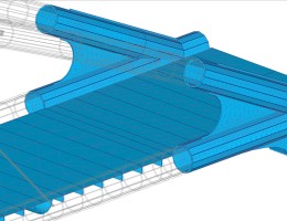
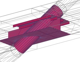
The upper bracing of the arch structure was studied with several variants and finally the “K” truss system was selected. The diameters of the crosslink tubes were determined by the needs of the end portal and the nodes near it. In order not to have to increase the tube diameters, we designed gusset plate connections hidden in the lower nodes. We were able to gradually reduce the wall thicknesses of the bars above while leaving the gusset plates. For the more complex nodes such as crosslink nodes, rod-link nodes, and the shoulder of the arch and tie girder connections, more detailed finite element shell models were made and the reference stresses were examined on them.
Due to the network system and the low dead load, great attention had to be paid to the rod regulation at the riverbed elements. With a possibly poorly chosen construction sequence and without the tensioning of the rods, pressure could have been developed in the rods, even under the effect only of dead load. For all these reasons, we applied dense supporting during assembly and the rods had to be inserted in a given order and the supports had to be removed in a given order. The rod tensioning was executed in 13 phases.

