Modeling of construction stages
Considering the construction stages can be particularly important during the design process if the structural framework differs from the final state or if structural elements are subjected to significantly different loading conditions during construction.
The conventional approach uses a single structural model that includes all elements, potentially leading to results from finite element analysis that deviate significantly from reality. Modeling construction stages eliminates this issue by creating separate sub-models for each stage and summarizing the results. This approach accounts for element construction, demolition, or strengthening, as well as the effects of construction loads and changes in the structural framework.

Modeling construction process
The module enables step-by-step simulation of the construction process. For example, in the case of a steel-framed hall, the process can be modeled from erecting the columns to lifting the roof structure and analyzing the final state.
Modeling demolition process, partial dismantling of structures
The module is also suitable to simulate the demolition process of buildings and other structures, tracking the redistribution of internal forces due to the removal of elements and analyzing the structural behavior. This ensures and verifies the stability of the structure during demolition. Additionally, the module can check the stability and load-bearing capacity of partially dismantled structures during the demolition and in its final state.
Verification of retrofitted and strengthened structures
The module is useful for verifying retrofittings and strengthenings (e.g., strengthening steel sections by welding plates, jacketing of columns, reinforcing masonry walls, replacing weak masonry columns with reinforced concrete columns, etc.) and analyzing the resulting changes in structural behavior.
Modeling structural damage
The module allows for modeling damaged or failed structures. By simulating the effects of corrosion, material defects, or extreme damage, assessment of the severity of the damage, the remaining load-bearing capacity of the structure, and the redistribution of internal forces within the damaged system is possible. This is essential for planning repairs and renovations or determining whether a damaged structure can remain in operation.
Modeling bridge launching process
Certain bridge types are constructed using the launching method, where the structural framework, loads, supports, and internal forces change throughout construction. Additionally, temporary support structures are required, and their adequacy must also be verified. The STG module allows for modeling the bridge launching process, enabling calculations of deflections, support reactions, internal forces and stresses at intermediate and final stages.
Analysing structural robustness and the possibility of progressive collapse
One of the highest-level applications of the module is evaluating the robustness of structures. By selectively removing key elements, the module can assist the assessment of the consequences of their loss, how the structure responds, whether it can withstand the redistribution of forces without collapsing, and whether it maintains functionality or at least stability. These analyses help in designing structural redundancy to enhance safety.
Key new features
Reinforced Concrete structures
Basic assumption in punching shear analysis within the RC3 module is that as the distance from the supported area increases, the punching perimeter also expands. However, in cases where this expansion is restricted due to specific conditions (e.g., near corners or openings), AXISVM X8 introduces two new methods to reduce the punching force as the distance from the supported area increases. During the analysis, integration can be performed at multiple locations along the way, allowing for the recalculation of the punching force as one moves away from the edge of a column, wall corner, or wall end.
The design of reinforced concrete columns has been enhanced with a rebar layout wizard function, which enables quick placement of reinforcement for rectangular and circular cross-sections with just a few clicks, simplifying the design process.
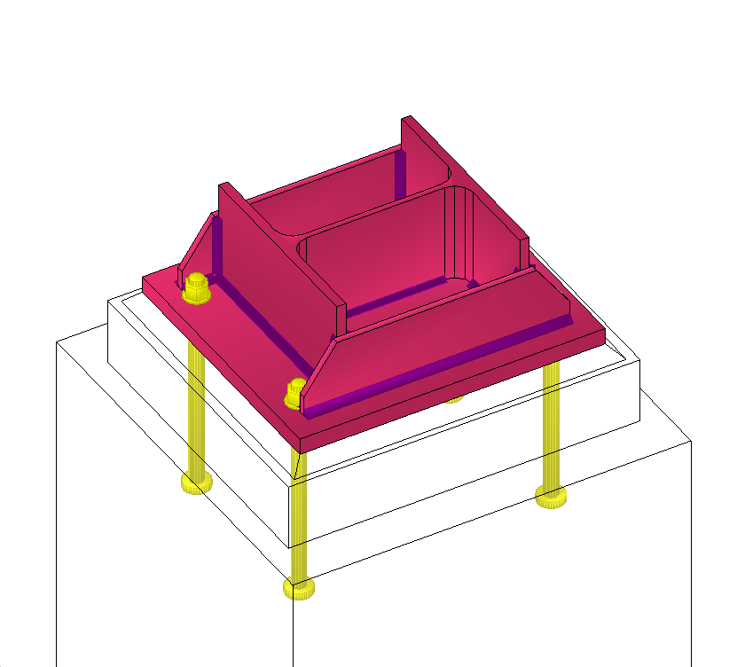
In the RC4 module, the foundation cover depth can have two different values (D1, D2). These values can be assigned by clicking on the foundation’s top-view diagram—quarter sections in the case of isolated footings and sides in the case of strip foundations.
Steel structures
Once the buckling analysis has been performed, it is possible to select the most relevant buckling mode within the SD1 module. Design member based on the obtained critical load factors and buckling shapes. Once a buckling mode is selected, the program automatically calculates the buckling length factor or the buckling length, streamlining and simplifying the design process.
A new section classification algorithm has been developed for the steel design modules, to perform the section classification and to provide the effective cross-section area under complex loading conditions. The new classifier iteratively accounts for centroid shifts in asymmetric Class 4 sections. Additionally, the details of the section classification are now included in the design calculations, making them fully documented. For Class 4 cross-sections, the program can perform normal force-shear-bending-torsion interaction checking and calculates von Mises stress based on the effective cross-section. This enhancement offers even more comprehensive and efficient tools for structural design.
Timber structures
Using the TD1 module, the buckling length can be defined directly alongside the buckling length factor when setting design parameters. After performing the buckling analysis, the TD1 module also allows users to select the most relevant buckling mode for the examined Design member based on the obtained critical load factors and buckling shapes. Once a buckling mode is selected, the program automatically calculates the buckling length factor or the buckling length, assisting and simplifying the design process.
Computational Enhancements
The calculation of lateral-torsional buckling load factors in buckling analysis has been refined for variable cross-section beams with seven degrees of freedom. Additionally, link elements and rigid bodies now possess geometric stiffness, enabling more accurate determination of critical load factors for structures such as eccentrically modeled beams and main girders loaded on their top flange.
For estimating support stiffness based on soil and foundation parameters, the program now automatically suggests the equivalent rectangle side lengths when using the Winkler (Steinbrenner) stress distribution method.
The KFI parameters of consequence classes can now be considered as partial factor multipliers when generating load combinations.
The SWG module’s snow load calculations have been updated according to Austrian NA, while the WIND and SWG modules now include roughness calculations according to Polish and new zone categories as per German NAs. Starting in April 2025, the SWG module will also comply with the UK National Annex, ensuring alignment with international standards.
During structural analysis, the system records and logs error and warning messages with accurate timestamps, which can be accessed at any time through a dedicated dialog within the program. The standard selection dialog now displays the full names of the incorporated standards.
Further developments
When renaming or labeling elements, it is now possible to display the internal unique identifier instead of the continuous numbering. This identifier remains unchanged throughout the model’s lifecycle, ideal to keep consistency between model file and model data in exported excel sheets.
Another new display feature allows the characteristics and support stiffness of line and surface supports to be shown in the model space as a labeling option. Additionally, more colors are available for customizing graphical symbols.
In X8, virtual strips function similarly to virtual beams. This means that when determining the centerline, virtual beams can also detect unmeshed areas, providing meaningful information even in the preprocessing phase.
A small enhancement in the editing interface now allows selected arcs to be easily converted into straight lines.
Steel Connection Design
SC1 module
The new version of the SC1 module is now capable of performing comprehensive verification of the welds of truss connections according to the EC 1993-1-8 (4.5.3.3) standard.
The stiffness of the designed connection can be automatically transferred to the global model space as end releases, enabling more accurate and efficient structural analysis.
More detailed information about the types of connections that can be analyzed, their applicability, and the methods for defining connections can be found on the module’s introduction page or in the manual.
►►► Drone view mode
Unique perspective for reviewing and presenting your design
Clipping regions and Transparent Scanners
Clipping regions allow for a quick exploration of the internal parts of the structure, including their results if needed. With clipping regions, a slice of the model enclosed by one, two, or three interactively adjustable cutting plane pairs can be displayed.
New Features in BIM
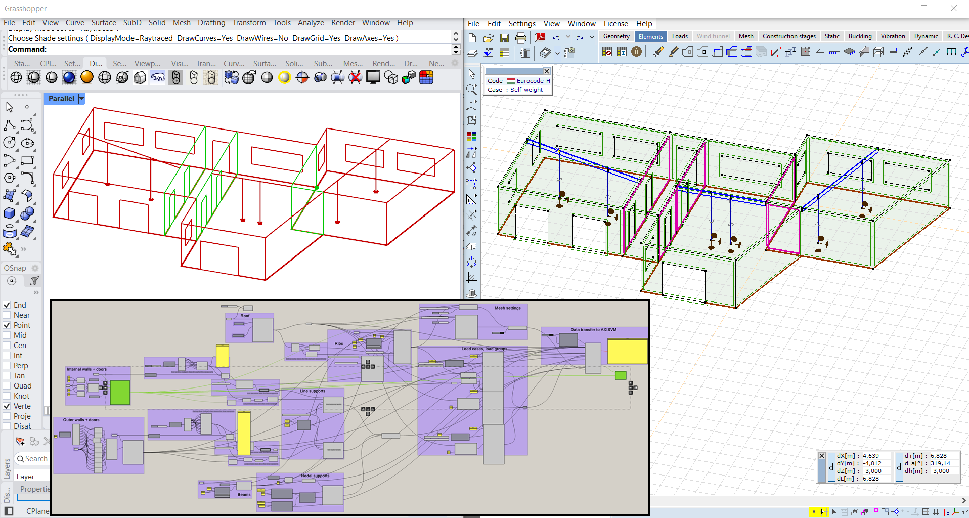
GrasshopperToAXISVM Add-on (v8.0)
General new features
The selected material, cross-section and CLT panel name is displayed at the bottom of the components. User may define warping transmissions (warping factors) and can assign the seismic isolator characteristics to springs easier. The analysis results can be imported for all structural members quicker.
User experience
AXISVM components provide Rhino preview from now on, making the identification of items much easier. Custom parts can be created and the parametric items can be highlighted in AXISVM. Flexible usage of AXISVM windows and files is ensured. The main items of existing *.axs files can be imported into Grasshopper and may be used for further actions (e.g. parametric load definition).
New load types
The Loads subcategory is extended with 6 new load types: moving load, nodal mass, fault in length, line tension-compression, influence line and concentrated surface load is available. Furthermore, the domain and load panel polyline loads may be assigned to structural members.

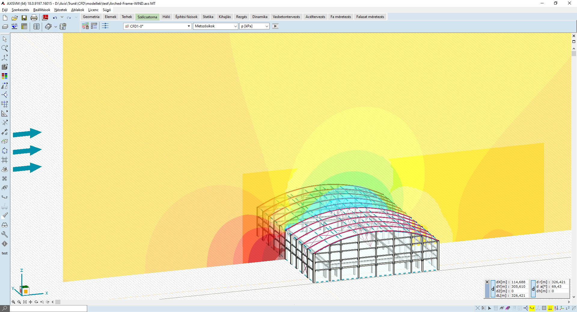
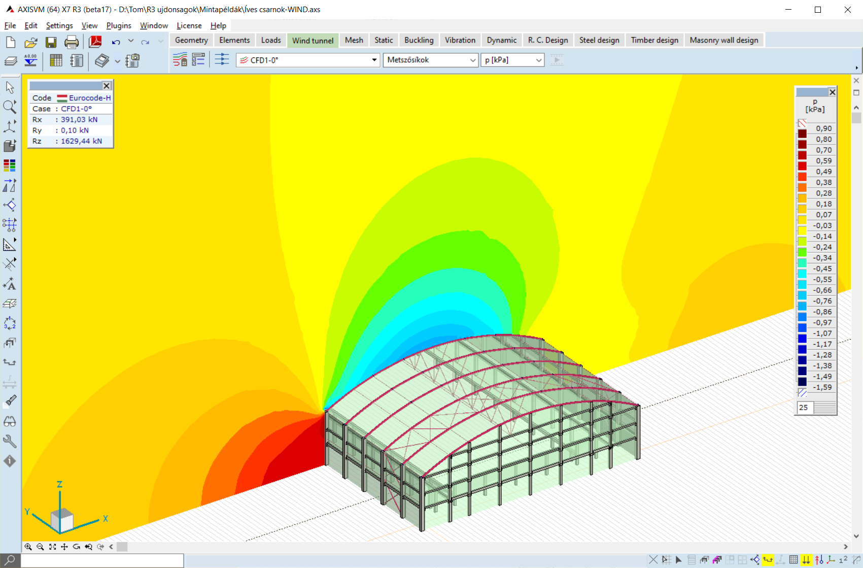
WIND module updates
In AXISVM X8, we have enhanced the WIND module to provide even more accurate and efficient analysis.
Streamline settings can now be customized per loadcase, allowing more accurate modelling. In addition, mesh quality control and automatic adjustments have been enhanced to improve convergence and stability of calculations.
The new reliability test ensures accurate and clear results, providing feedback to users on the correctness of the results.
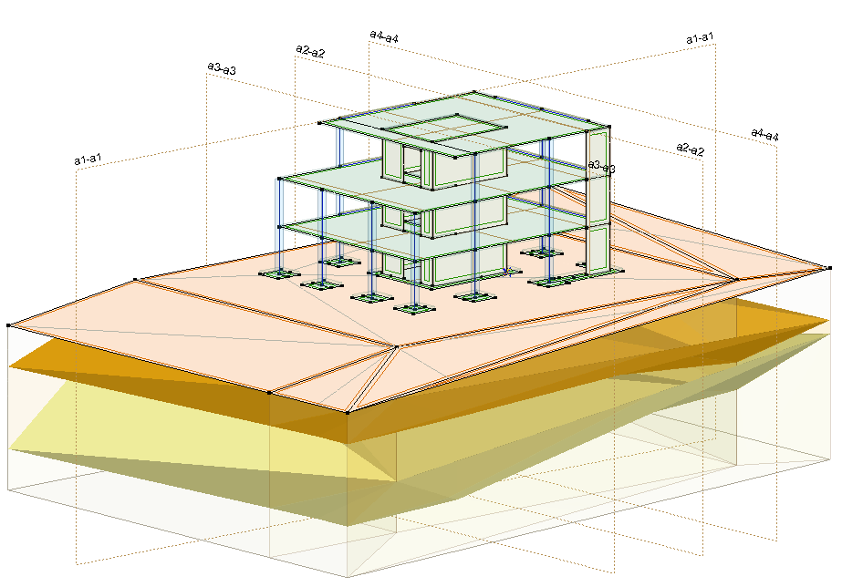
SOIL module updates
Consider the initial state
AXISVM X8 provides the capability to consider the initial state of the soil, which provides the possibility to take into account the pre-stressed state of the ground.
In the initial state, the soil is under stress due to its self-weight and other prior loads present on the soil, but the deformation is supposed to have already occurred and is considered to be zero.
This new function allows more accurate and realistic calculations, especially when complex soil layer conditions are taken into account.