GENERAL PURPOSE MODULES
IMP MODULE
Geometrics imperfections based on buckling shapes
SOIL MODULE
Modelling of the soil-structure interaction
IMP MODULE
Structural analysis is usually performed on an idealized, geometrically perfect model. However, nothing is perfect in the real world. The structural geometry, the material behaviour and the position of the loads are all imperfect. Geometrically and materially nonlinear analysis with imperfections included (GMNIA) may be used effectively instead of linear methods for strength and stability verification of structures, structural elements and details. This is especially true in the case of complex structural details and parts where the stability and load-bearing capacity can be hardly verified with simpler methods.
The IMP module of AxisVM allows users to account for such geometric imperfections, which can be created by scaling and then superimposing the buckling-mode shapes. The effect of imperfections can be taken into account via a geometrically nonlinear analysis on a load combination, which includes imperfection-type load cases.
Requirements / recommendations
NL or PNL (e.g. NL1S, PNL3P) configuration is required to account for geometric imperfections based on buckling mode shapes
DESIGN CODES
The IMP module is design code independent
CHARACTERISTICS
- scaling and superimposing of buckling mode shapes
- displaying of created imperfect geometries
- including imperfection-type load cases in load combinations
- performing nonlinear analysis on models with geometric imperfections
DETAILS
CREATING EQUIVALENT GEOMETRIC IMPERFECTIONS
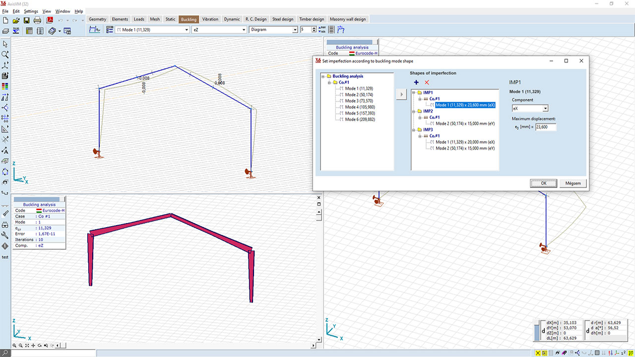
The imperfect geometry can be compiled from the mode-shapes obtained from a buckling analysis, even corresponding to multiple load cases. Displacement components and the respective maximum values for each buckling mode shape can be specified. The created geometric imperfections can be included in load combinations.
NONLINEAR ANLYSIS OF MODELS WITH EQUIVALENT GEOMETRIC IMPERFECTIONS
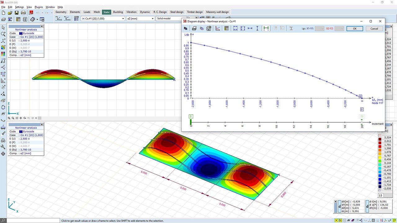
Internal forces may be obtained on models with geometric imperfection via a geometrically nonlinear analysis include large-displacement effects. The loss of stability mode can be determined with a displacement-controlled nonlinear analysis. Finite element simulation-based design is also possible by using nonlinear material models and geometric imperfections together.
STG MODULE
General description of the STG module
Considering construction stages is particularly important during the design process when the structural system changes compared to the final state, or when structural elements are subjected to significantly different loading conditions during construction (e.g., storage of building materials, cranes, temporary supports, lifting operations, etc.). Neglecting these effects and circumstances can lead to significant errors and incorrect assessment of structural behaviour and reliability.
The conventional modelling approach often involves creating a single structural model that includes all structural elements. During finite element analysis, the effects of all loads are calculated on this model, which may result in internal forces deviating from real conditions. For instance, in the case of a multi-story reinforced concrete building, axial forces, shear forces, and bending moments may develop in the elements of upper storeys due to the self-weight of columns and beams on the ground floor. In reality, the deformations caused by the self-weight of ground floor elements largely occur earlier and do not induce stresses in the upper elements since these deformations are compensated. Similarly, in the case of softer support conditions, the differential settlements caused by the self-weight of slabs on the lower levels can affect the loads and reinforcement requirements of slabs constructed on higher levels.
Modelling construction stages can address the aforementioned issues. In this approach, if linear analysis is performed, sub-models corresponding to each construction stage are analysed separately, and the results are combined. As a result, we can take into account, stage by stage, if an element has been built, demolished or reinforced. Additionally, it enables calculating the effects of construction loads and changes in the structural system.
Beyond modelling construction processes, the module provides the capability for:
- modelling demolition processes,
- analysing partially demolished and reinforced structures,
- assessing structural reinforcements and replacements, as well as verifying the reinforced structure,
- evaluating structural damage (e.g., checking corroded steel structures),
- analysing progressive collapse and structural robustness,
- assessing bridge launching process.
Requirements
- No requirements
STANDARDS
The STG module is design code independent
CHARACTERISTICS
- Modeling of construction and demolition processes.
- Numerous additional applications (structural strengthening, consideration of structural damage, evaluation of structural robustness, bridge launching, etc.).
- The structural model and the properties of structural elements can be modified between construction phases.
- Permanent and temporary loads during construction.
- The most important design modules are available in all construction phases.
- Consideration of initial conditions (e.g., soil stress state).
- Construction stage results can be easily documented in the form of drawings and tables.
- Intuitive, easy-to-learn user interface.
DETAILS
MASTER MODEL
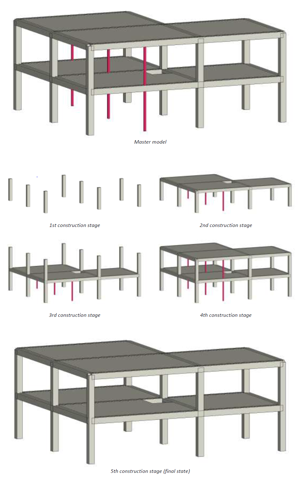
In the case of modeling the construction process, we must follow the usual procedure and build the finite element model accordingly. There is no need to create separate submodels for each construction stages, which significantly shortens the modeling process.
However, the created model must include all elements and loads that we want to consider during the analysis of the construction/demolition, regardless of whether these elements and loads are present in the final state of the structure. This model is called the master model. When defining the construction stages, the active elements are selected from this model.
The attached figure illustrates the master model of a reinforced concrete structure built with temporary supports, along with the corresponding states for each stage.
Cumulative displacement
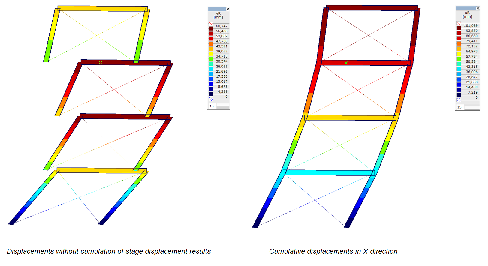
The consecutive construction stages are always analysed only for the differential loads, and the static results are superimposed. Due to the nature of the calculation, displacement results contain discontinuities at the boundaries of the construction stages, as the displacements must be interpreted relative to the deformed shape obtained in the preceding stage. This does not always cause issues; however, in certain cases, it complicates the interpretation of results (e.g., during the construction of multi-story buildings with significant top displacements).
In order to achieve the deformed shape according to conventional engineering principles, the displacement results of the construction stage need to be aligned/cumulated. This alignment can be controlled according to three displacement degrees of freedom: X, Y, and Z displacements. The software aligns the displacement results at the boundaries of the construction stage according to the activated degrees of freedom.
Loads of construction stages
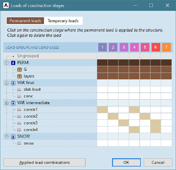
During the construction or demolition process, loads can be assigned in a tabular format by clicking on the cell corresponding to the load case (load group) row and the designated construction stage column. Load cases and their associated loads must be predefined in the master model.
Construction loads can be either permanent or temporary. Permanent loads typically include self-weight, while temporary loads may consist of workers, tools, and stored construction materials. Based on these loads, the software automatically generates the relevant load combinations for each construction stage.
SOIL MODULE
The SOIL module allows more precise modelling and consideration of the soil-structure interaction. In the so-called direct approach, the soil and the structure are modelled and analysed together. The settlements and the induced internal forces can be calculated, as well as the stresses and strains in the soil beneath and around the structure. The software is able to generate a spatial soil model with layers based on the given borehole samples. A further possibility is that the Winkler stiffnesses for supports can be estimated based on interpolated soil profiles.
STANDARS
The SOIL module is design code independent.
CHARACTERISTICS
- User defined borehole samples
- Interpolated soil layer profiles
- Calculation of Winkler stiffness for conventional support elements using interpolated profiles
- Generation of soil model using solid finite elements
- Modelling of soil-structure interaction
DETAILS
Definition of borehole samples
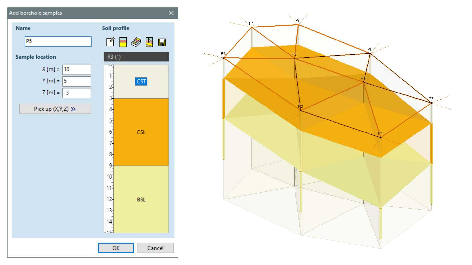
The borehole sample is a soil layer profile recorded at a given spatial position in the global space of the model. The borehole samples are connected with a triangular mesh as a basis for the interpolation of the layers inside and outside the polygon defined by the samples.
Soil model

The soil model, built from solid elements, is used to more accurately model the interaction between the soil and the building structure. The stresses and strains in the soil induced by the loads can also be calculated. When specifying a soil model, the building structure is not supported by nodal, line or surface supports but by the soil model itself. In this case, the pad, strip and slab footings must be modelled with their actual physical dimensions as domains in contact with the soil. In order to build a soil model, at least one soil modelling domain needs to be specified. This is a planar polygon similar in geometry to conventional structural domains. The soil model is a region of space situated below soil modelling domain and meshed with solid finite elements, where the properties of the solid elements follow the layer profiles defined by the borehole samples.
Solid finite elements
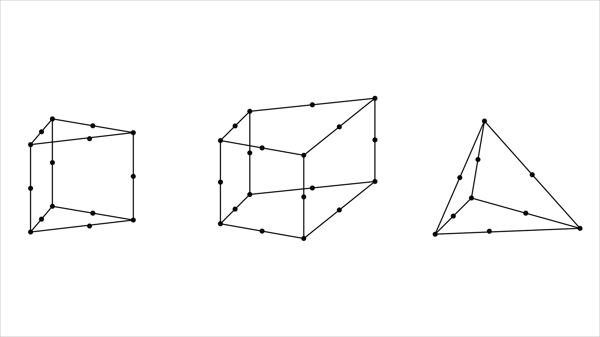
The shape of the generated solid elements can be hexahedron or wedge-shaped or a mixture of both, or they can also be tetrahedron shaped. The volumetric mesh is constructed by vertical projection of the surface mesh. When using triangular or rectangular solid elements, the layer boundaries are handled by element shortening, but in the case of tetrahedron meshing, the size and number of tetrahedra are dynamically adapted to the layer thickness.
Soil-structure interaction
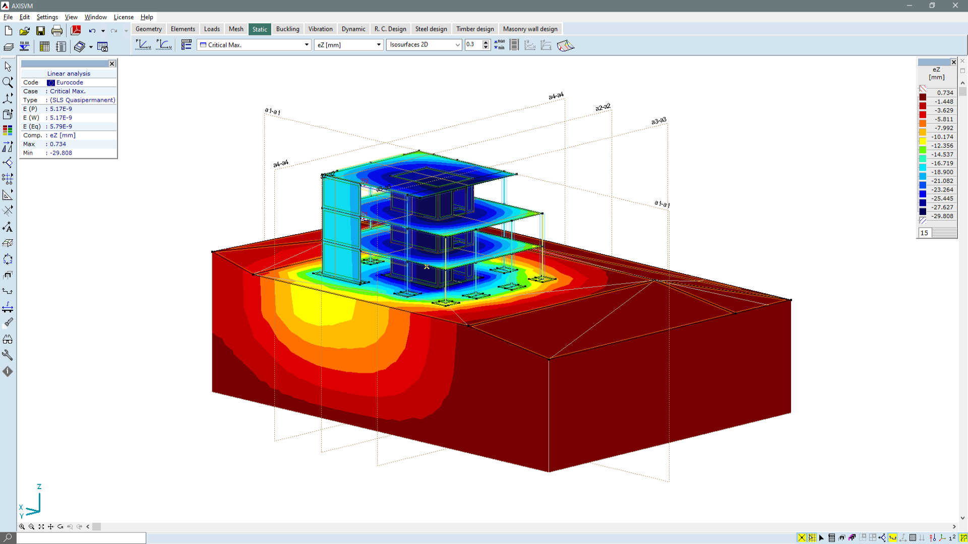
The soil model can follow the interaction between the soil and the structure more accurately than a calculation where the soil is modelled with springs. Consequently, the additional internal forces induced by relative settlements can be more accurately calculated. By modelling the soil around the structure with solid elements, there is no need to estimate soil stiffness based on different theories, and the model can track changes in stiffness due to variation in subsoil conditions. The soil model can be effectively used in the case of pad, strip and slab footings, even with complex geometries.