GENERATION OF METEOROLOGICAL LOADS
The highly detailed verification rules of the standards often require the use of computer programs. Countless combinations and load cases must be taken into account when designing the structures and finding optimal solutions, which can no longer be handled by manual calculations. This fact is especially actual for meteorological loads.
AXISVM’s modules help designers to do this by automatically generating the snow and wind loads required by the standard (SWG module) or converting the results of digital wind tunnel simulations into wind loads (WIND module) and managing them in a complex way.

SWG MODULE
Automatic generation of snow and wind loads for standard structures
WIND MODULE
Wind load determination using digital wind tunnel simulation for any structures
SWG MODULE
In the case of dynamic analysis, the program determines the displacements and internal forces of the structure for each time step, corresponding to the defined dynamic loads. The analysis can be carried out by considering linear or nonlinear material behavior. Geometric nonlinearity can also be considered.
The following dynamic actions can be applied:
dynamic point load acting on a node, domain, or load panel
distributed surface load on a domain or load panel
node or nodal support acceleration
With these dynamic loads, the DYN module is able to conduct time-history analysis (e.g. earthquake), shock wave analysis (e.g. blast), and forced vibration analysis (e.g. machinery).
Requirements / recommendations
in order to perform nonlinear dynamic analysis, the nonlinear (NL) basic package is needed
DESIGN CODES
Eurocode1
EN 1991-1-3
EN 1991-1-4
Swiss standard
SIA 261
Italian standard
NTC
CHARACTERISTICS
- automatic generation of snow and wind loads according to the standard
- individual parameters that can be specified according to the requirements of national annexes
- the meteorological loads are distributed on load panels covering the building or structure
- load zones are created based on the type and geometry of the structure
- the algorithm handles both undrifted and drifted snow load cases
- the total wind load of a complex structure can be assembled by the loads of the implemented basic structural types
- the generated meteorological loads are considered as static loads; their dynamic effect cannot be examined
DETAILS
AUTOMATIC GENERATION OF LOAD CASES
USING LOAD PANELS
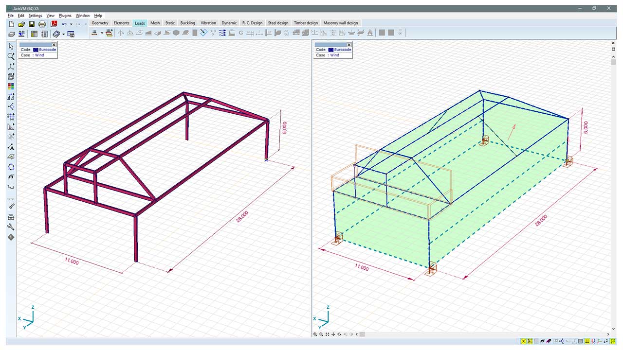
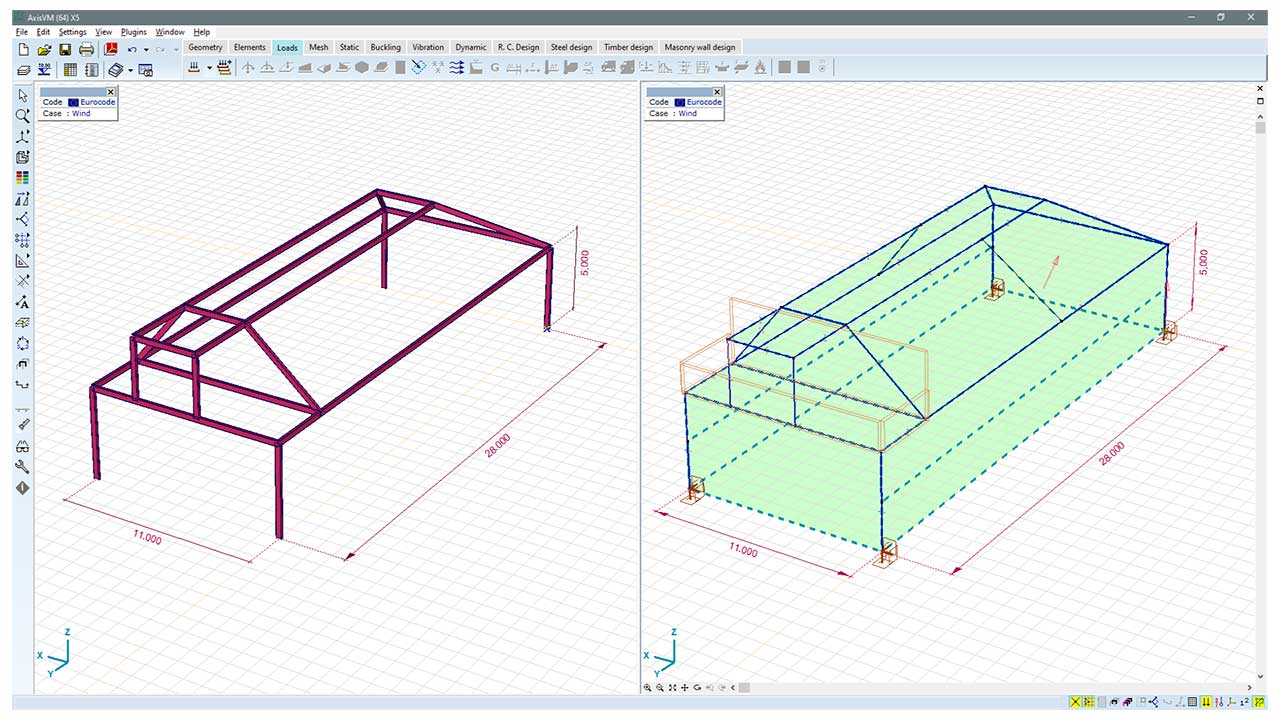
The module requires the use of AxisVM load panel tool. The boundary planes of the structure must be covered by load panels, then the snow and wind loads are distributed on these panels considering different load zones.
The load panel has no structural role in the model. It only serves to distribute the loads placed on it to the structural elements.
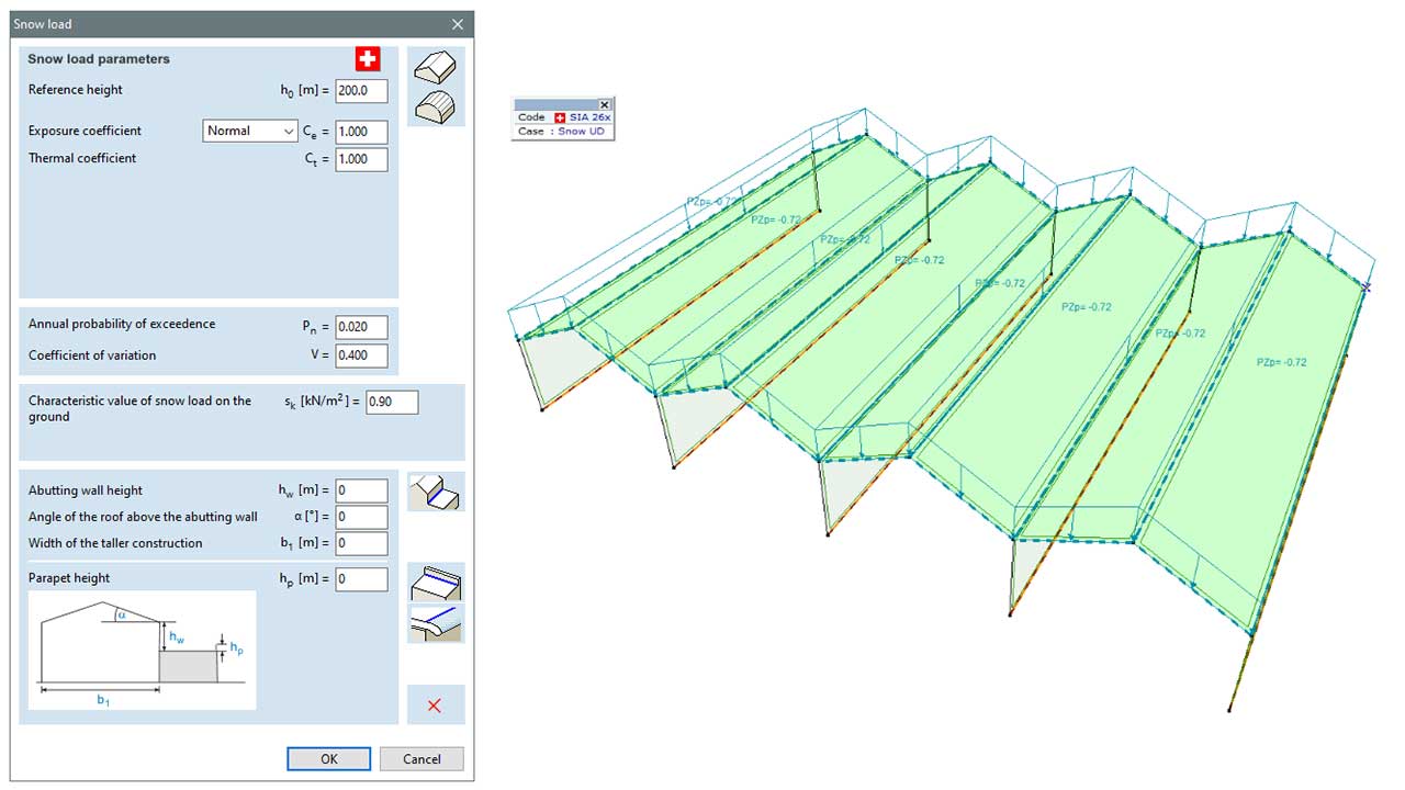
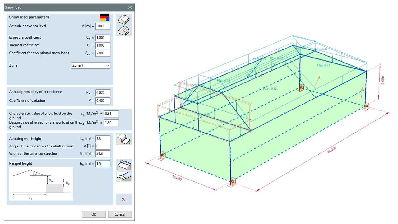
SNOW LOAD PARAMETERS
SNOW LOAD – SPECIAL OPTIONS
The module can calculate snow load shape coefficients for roofs abutting and close to taller construction works or having a parapet which acts as an obstruction. It can take into account the effect of overhanging snow on roof edges. Parameters are stored with the edges so different roof edges can have different parameters.
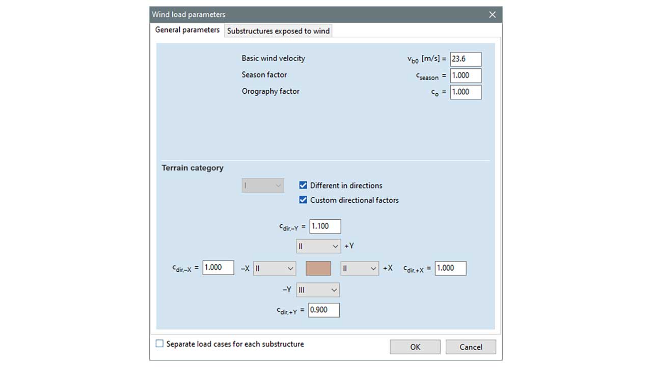
As the wind direction, the global X, Y directions of the model and the directions enclosing an angle of 45 degrees with them are taken into account.
WIND LOAD PARAMETERS
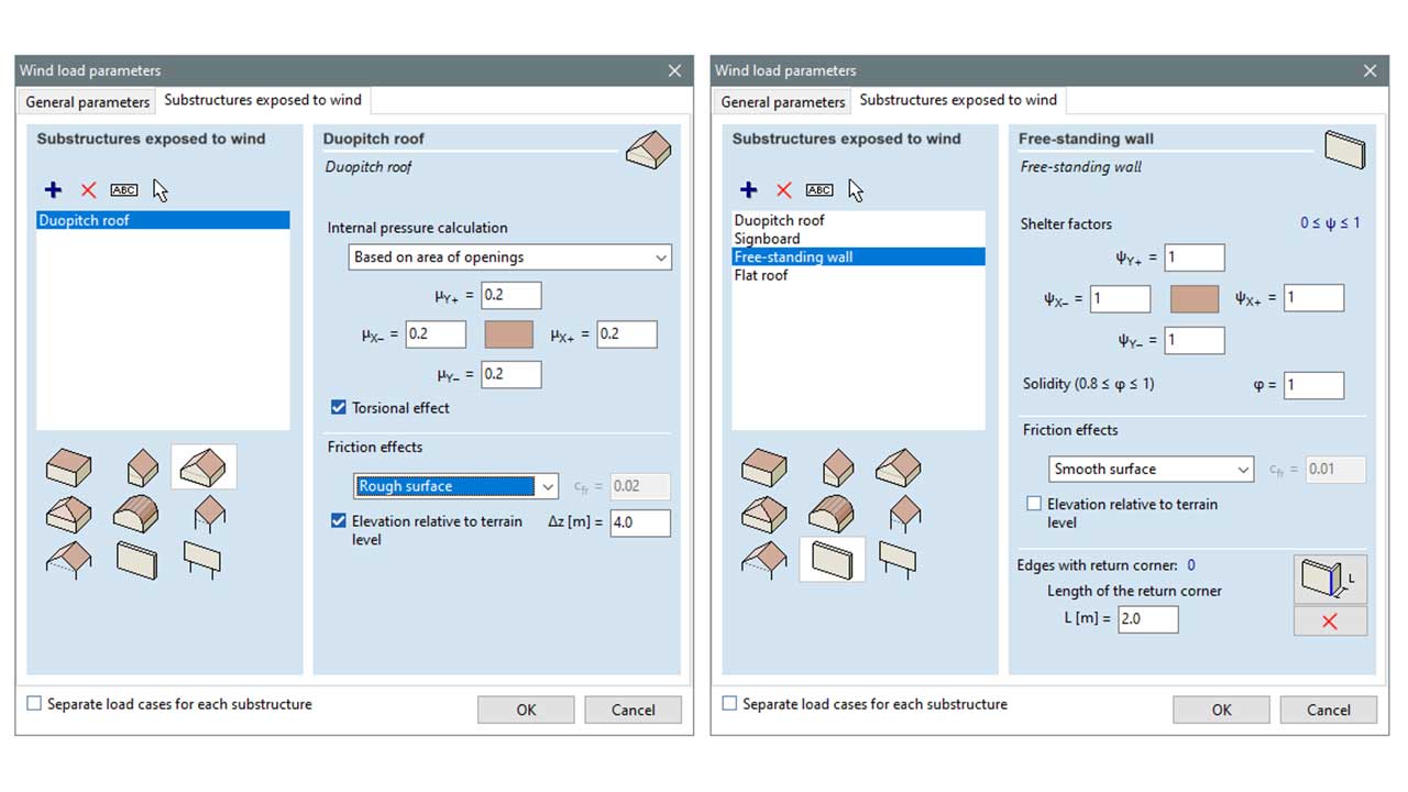
WIND LOAD – CLASSIFICATION OF STRUCTURES EXPOSED TO WIND
In the module, wind load can be assigned and generated to substructures defined by the selected parts of the model. For each substructure, a primary structural model type according to the standard has to be assigned. In case of building type substructures: flat roof, monopitch roof, duopitch roof, hip roof and barrel roof types are available. In addition, canopies and free-standing walls and signboards can also be defined.
The implemented method allows the user to approximate the wind load of complex structure with different standard models, and the program can combine wind loads for such substructures into a general wind load for the whole structure.
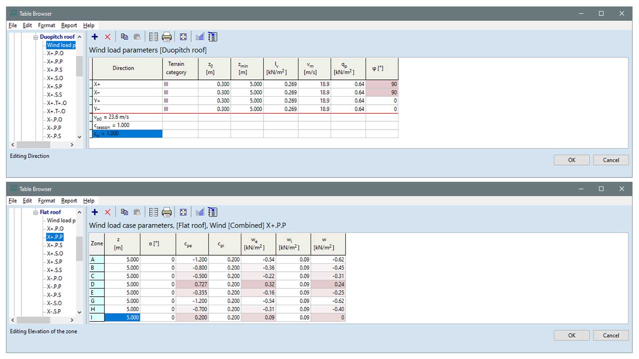
TABLE OF WIND LOAD PARAMETERS
After the wind loads have been generated, all the data related to their calculation is available in the Table Browser under Loads/ Wind load on substructures. Wind load parameters summarize the values that are not load case specific. Wind load case parameters summarize load case specific parameters for each wind load case. These parameters are grouped by the zones generated on the selected load panels.
WIND MODULE
In many cases, the specifications for typical structures discussed in the standards are not applicable to the analysis of more complex spatial structures. For wind loads, it may be necessary to take pressure values from flow simulation and/or wind tunnel experiments. The WIND module offers support to designers in such cases. The WIND module enables the determination of wind loads using a digital wind tunnel simulation. The wind pressure field obtained from the wind tunnel simulation is converted to the structure, forming load cases for each specified wind direction.
Requirements / recommendations
Useful for non-standard structure types to perform digital wind tunnel simulation
DESIGN CODES
Eurocode1
EN 1991-1-3
Swiss standard
SIA 261
CHARACTERISTICS
- recommended for irregular geometries or structures with specific loads not covered by the standard
- can only be used for steady-state (static) pressure, not for dynamic loads
- can be used with wind profile specifications of national standards and with custom specified wind profiles
- automatic generation of wind loads based on wind tunnel pressure values
- the program places the loads on the load panels enclosing the building/structure or directly on the structural elements
- the program considers wind loads as static loads and cannot take into account their dynamic effects
- primarily proposed to determine external pressure factors, determination of internal pressure factors can be difficult
- structure behaves as a rigid-body in the wind tunnel simulation, deformation of the structure is not taken into account
DETAILS
DIGITAL WIND TUNNEL SIMULATION
AXISVM uses the OpenFOAM® (Open Field Operation And Manipulation) open source C++ toolkit to perform wind tunnel simulations.
For more information about OpenFOAM®, please visit
LOAD CASES
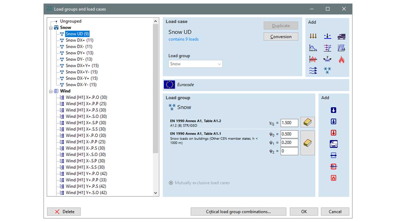
Users can define load cases for each wind direction within the CFD load group. There can be any number of load cases in a CFD load group, but within a load group the wind profile is the same for all load cases. Within a load group the load cases are mutually exclusive.
The user can choose between these two recommendations:
- CCIP-016
- SCI P354
USING LOAD PANELS
Load panels are required to enclose the surfaces of the building/structure that are not included in the model but are directly affected by the wind. For example roof panels, glass walls, windows, etc.
The program places the generated wind load on the load panels of the structure.
In areas of the building/structure not covered by load panels, the program directly applies wind loads to the structural elements.
Load panels do not participate in the structural analysis, its only provide the distribution of the applied loads to the structure.
TERRAIN
Z0 represents the terrain level in the global coordinate system of the model.
The model is cut along this height with a horizontal plane, and only the part above the plane is placed into the wind tunnel simulation.
If we want to consider the windflow influencing effects of surrounding buildings, we can define load panels enclosing the volumes of neighboring buildings.
ANALYSIS
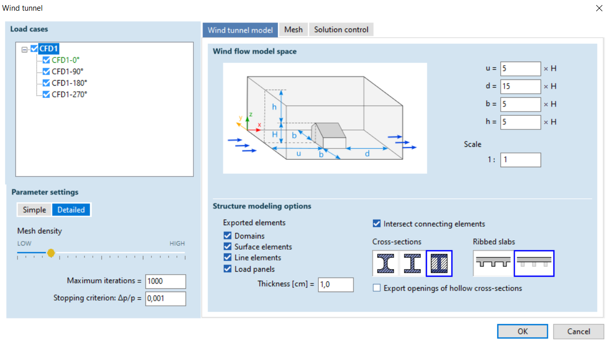
For the analysis, we can specify the size of the wind tunnel model space based on the height (H) of the building.
We can set which structural elements and their level of detail to consider in the wind tunnel simulation. For example, we can specify whether the beam elements should appear in the model space with only their enclosing polygons or with their actual cross-sectional shapes.
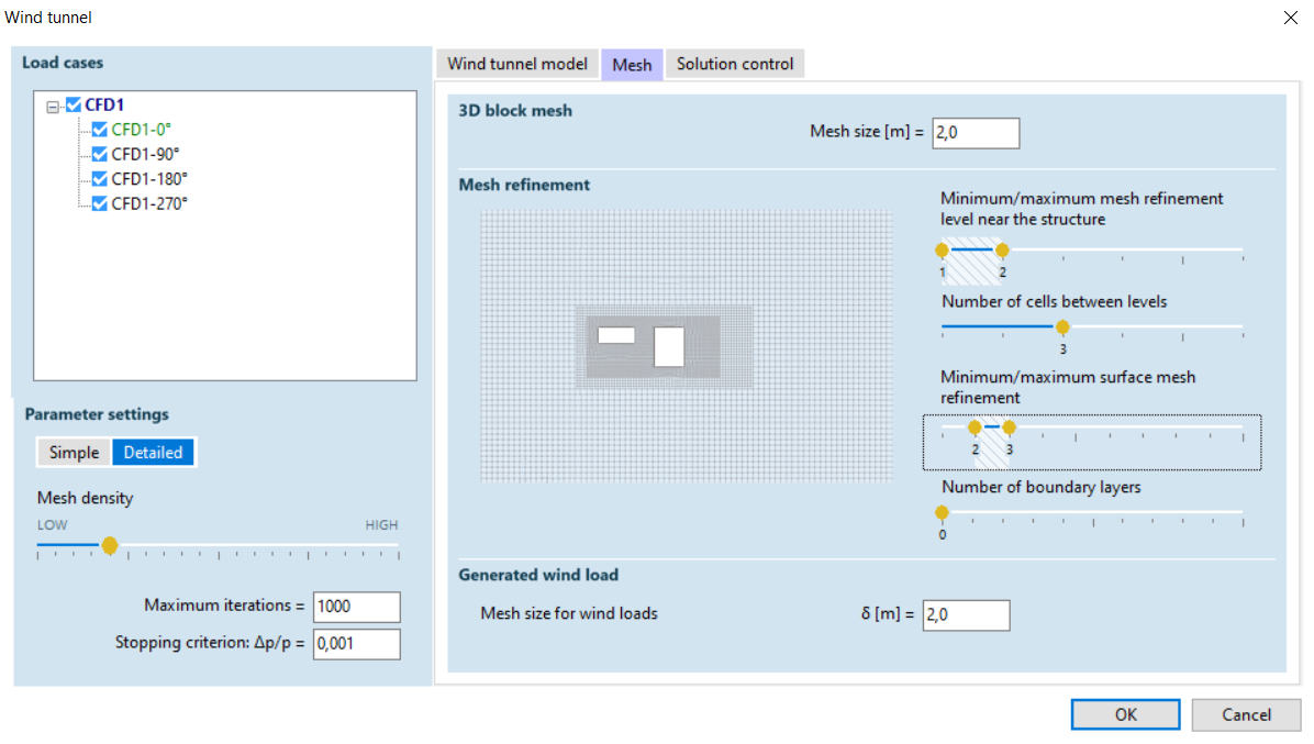
For the wind tunnel analysis, the meshing parameters can be set.
Based on the set parameters, the program divides the model space into cells with a gradually densified mesh near the structure.
Achieving accurate results, the meshing parameters must be set depending on the geometric complexity of the structure.
RESULTS
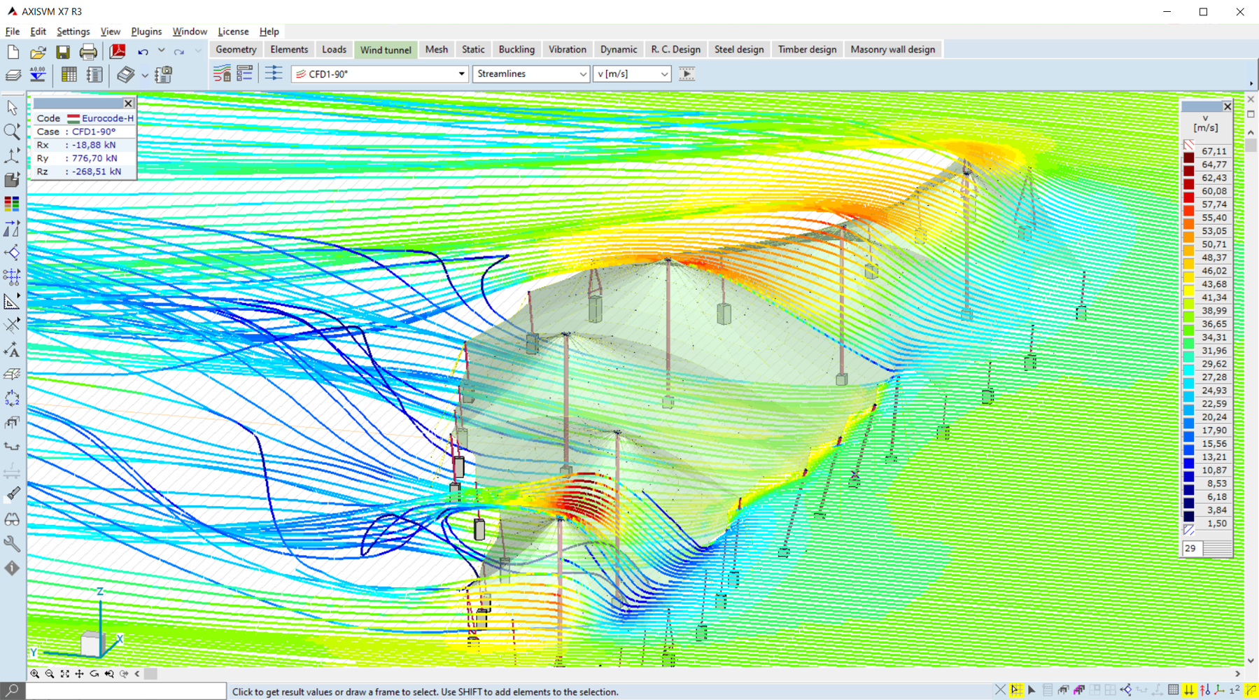
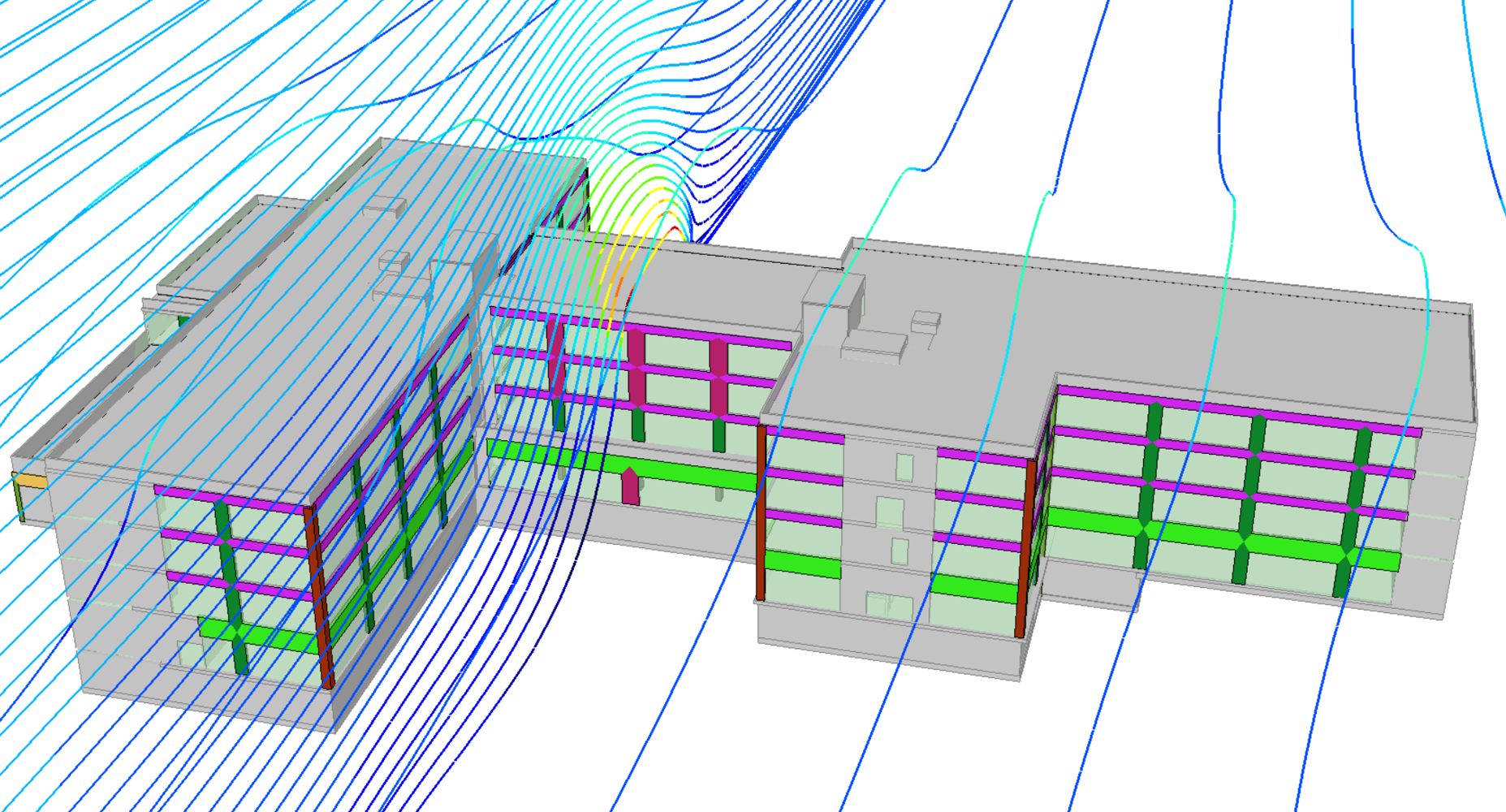
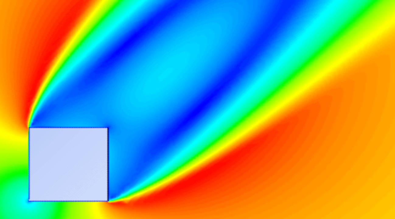
After the wind tunnel simulation, the program can display streamlines, wind speed, pressure values, and generated wind loads for each wind direction.
These results can be displayed in color scale diagrams, section planes, and animations.
The generated wind load cases can be run in the structural analysis, similar to other load cases.

