CUSTOMER PROJECTS
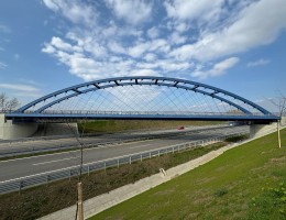
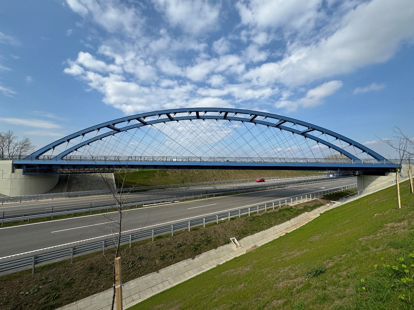
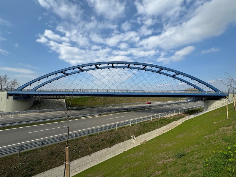
M6 motorway - railway arch bridge at Bóly
BÓLY, HUNGARY
Bridge Structural Designer:
Designers:
Structural Calculations:
Year of Commissioning:
MSc Mérnöki Tervező és Tanácsadó Kft.
Mátyás Gyurity, András Póta, Dávid Németh
András Póta, Dávid Német
2022
PROJECT DESCRIPTION
Brief Description of the Project
The construction of the final section of the M6 motorway between Bóly and Ivándárda, part of the Pan-European Transport Corridor V/c, began in 2021. The route crosses the Villány-Mohács railway line, making it necessary to construct a new railway structure.
Brief Description of the Structure
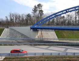
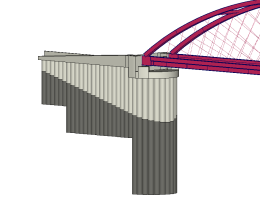
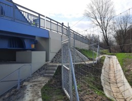
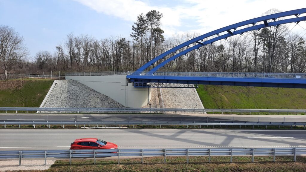
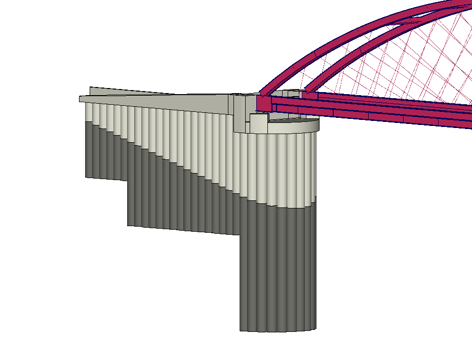
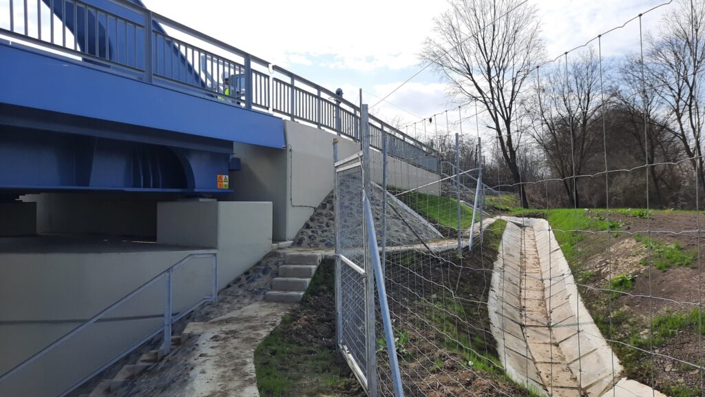
The foundation, serving also as the abutment wall, consists of a row of 100 cm diameter CFA piles designed in “J” shape in plan view, tied together with a semi-circular structural beam and backward extending wing wall beams.
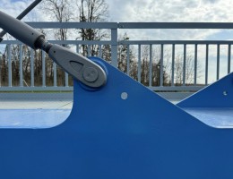
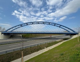
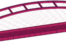
The superstructure is a single-span network arch bridge with a span length of 72.00 m and a rise height of 11.50 m. The arches run in parallel planes, spaced 5.60 m apart, braced in a Vierendeel-like manner. The arches are made of constant-height hollow sections that slightly flare towards the abutments. The stiffening girder is an asymmetric cap girder, where diaphragms ensure the integrated behaviour of the webs while providing adequate stiffness for the cable anchorage. The orthotropic deck consists of a steel plate stiffened by flat steel longitudinal ribs and it is supported by longitudinal and transverse girders.
General Data of the Bridge:
Span: 72.00 m
Clear opening: 66.50 m
Rise height: 11.50 m
Main girder spacing: 5.60 m
AxisVM Finite Element Model Used for Structural Design:
- For the substructure analysis, a combined model of three-dimensional beam and shell elements was developed, enabling assessment based on actual support conditions calculated using geotechnical parameters. The pile wall abutment design, together with the head and structural beams, ensures proper support for the enclosed soil mass, the direct bearing of railway loads, and the absorption of vertical and horizontal forces transmitted from the bridge.
- The check of the load-bearing elements of the superstructure, as well as the serviceability and dynamic tests, were conducted using a combined model of global spatial beams and shell elements.
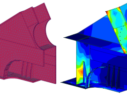
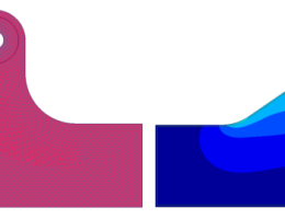
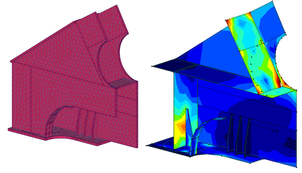
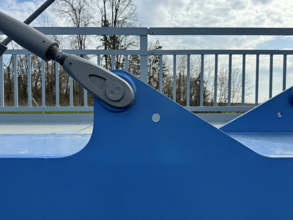
- Local shell models were used to check critical parts of the structure. This model provided a more accurate understanding was gained of the actual force interactions and stress concentration environment at the complex joint formed at the connection between the arch and the stiffening girder, as well as at the cable anchorage tabs, which aided in determining the optimal structural configuration.

