REINFORCED CONCRETE STRUCTURES
Due to its wide range of applications, reinforced concrete is considered to be one of the most universal construction materials today. Many structural engineers in Europe and around the world use AxisVM in everyday practice for the design of buildings, bridges, stadiums, industrial, and geotechnical structures. AxisVM has numerous design modules available for the design of reinforced concrete structures covering foundations, walls, cores, slabs, columns, and beams, including punching analysis and modeling of post-tensioned beams and floors.

RC1 MODULE
Design of plates, shells and stab-on-grade foundation
RC2 MODULE
Design of columns and beam
RC3 MODULE
Punching and shear design of RC slabs
RC4 MODULE
Design of plates, shells and stab-on-grade foundation
RC5 MODULE
Design of columns and beam
RC6 MODULE
Punching and shear design of RC slabs
PS1 MODULE
Analysis of post-tensioned beams and surfaces
RC8-B MODULE
Fire design of reinforced concrete beams and columns
RC8-S MODULE
Fire design of reinforced concrete surfaces
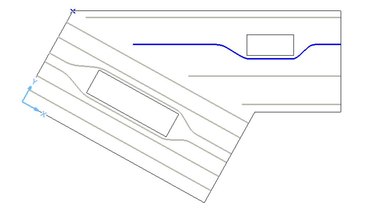
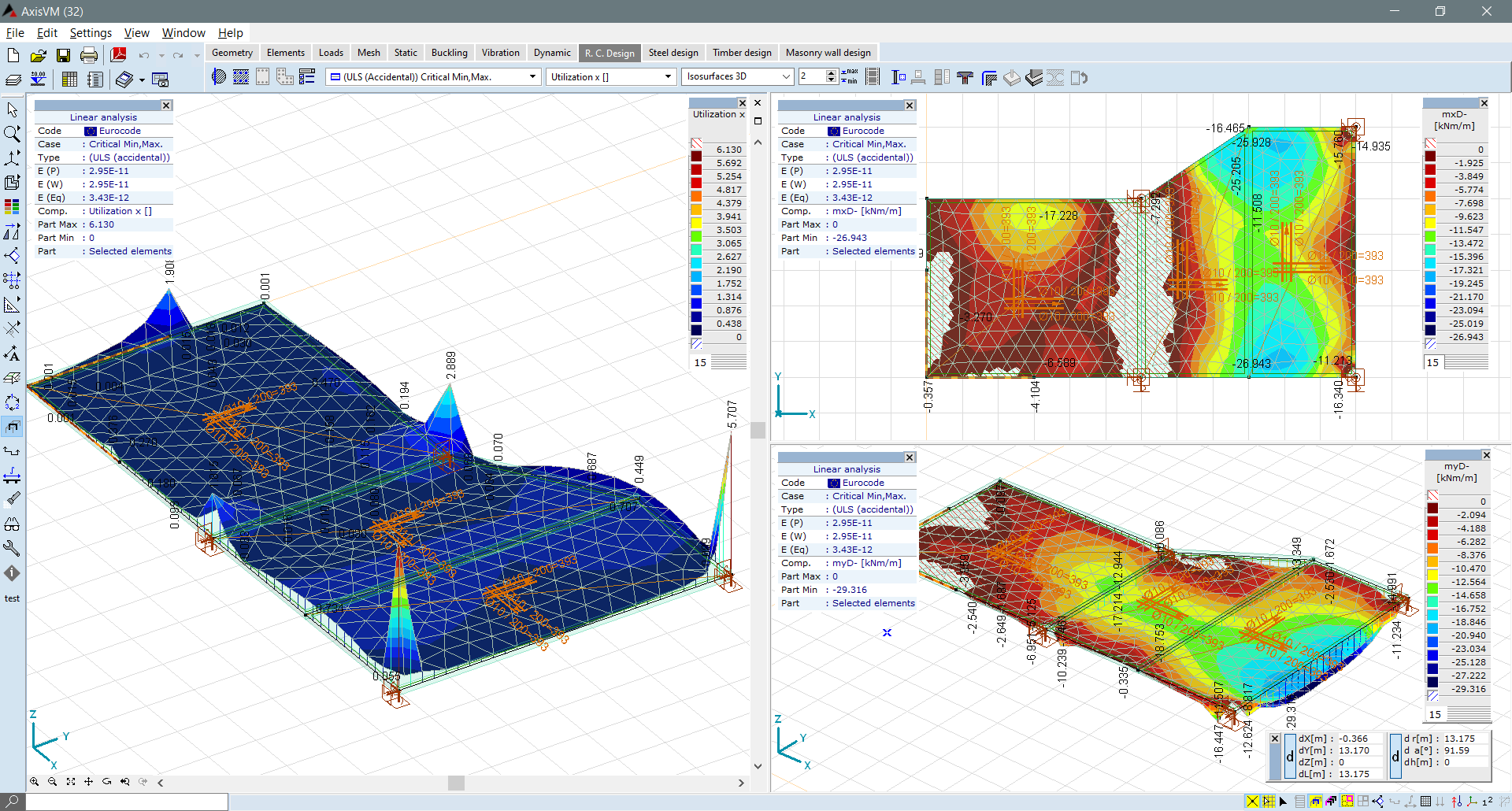
RC1 MODULE
The RC1 module is made for the design of reinforced concrete surfaces (membranes, plates and shells) with orthogonal or skew reinforcement. Multi-layered, actual reinforcement can be assigned to surface elements (based on the calculated reinforcement), which is considered in the calculation of crack width and nonlinear deformations.
Requirements / recommendations
at least an NL2 configuration is required for the analysis of nonlinear deflection of plates and shells
DESIGN CODES
Eurocode2
EN 1992-1-1
Swiss standard
SIA 262
Italian standard
NTC
CHARACTERISTICS
- graphical representation of the required reinforcement, actual reinforcement and their difference
- lexible and user-friendly definition of design parameters and rebars
- definition of actual reinforcement for a whole domain or for an arbitrary polygonal shape
- verification of compliance with design code detailing rules
- calculation of required reinforcement for a specific crack width limit value
DETAILS
SKEW REINFORCEMENT
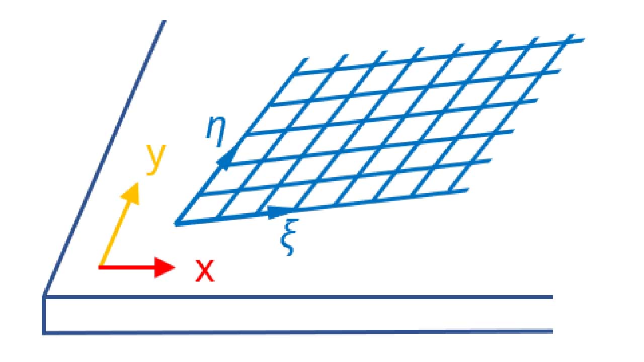
Orthogonal reinforcement mesh with reinforcement directions different than the x and y local axes and reinforcement mesh with arbitrary reinforcement directions are called skew reinforcement. A sandwich model with three layers is used for the calculation of required reinforcement of skewed reinforced surfaces. In order to find optimal reinforcement, the thickness of the layers is iteratively changed.
CRACK WIDTH
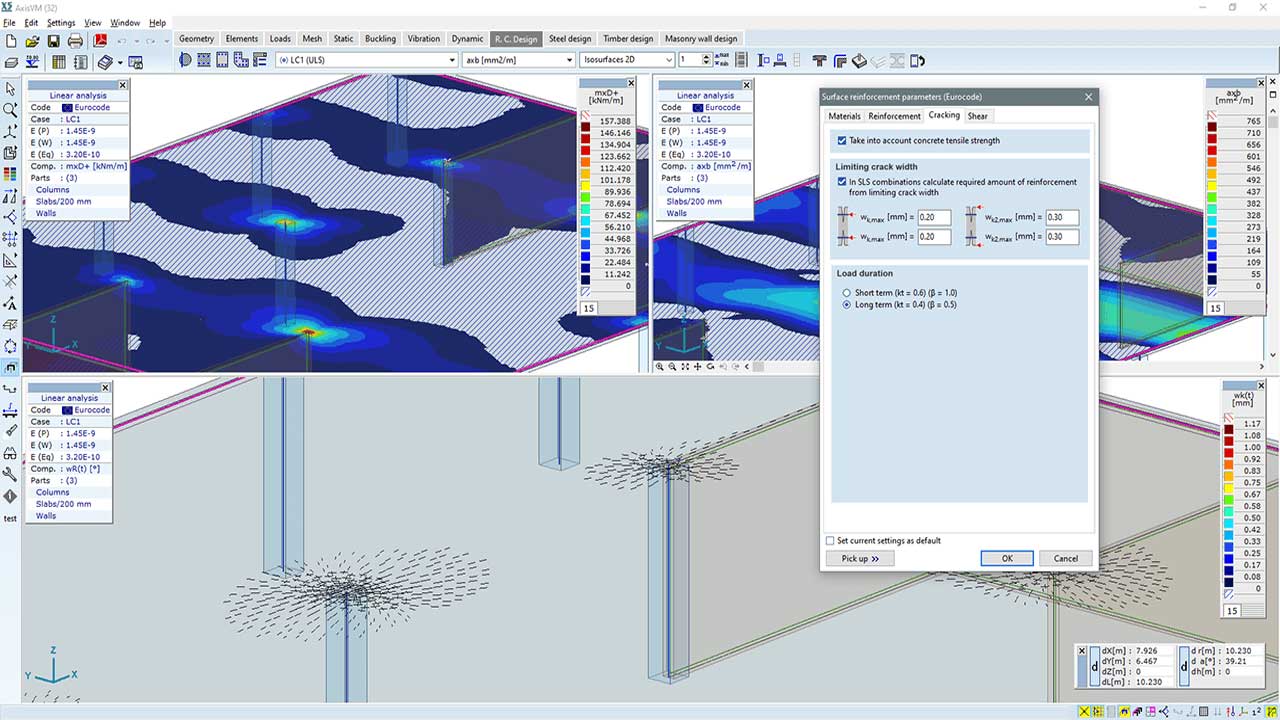
If actual reinforcement is assigned to the surfaces, AxisVM calculates the width and direction of the cracks and then plots the cracks on the surfaces. The required reinforcement can be calculated from the specified crack width limit corresponding to the top and bottom sides.
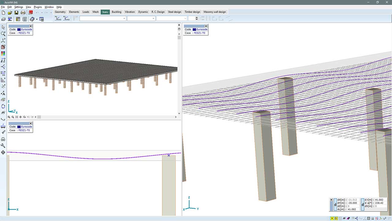
NONLINEAR DEFLECTION
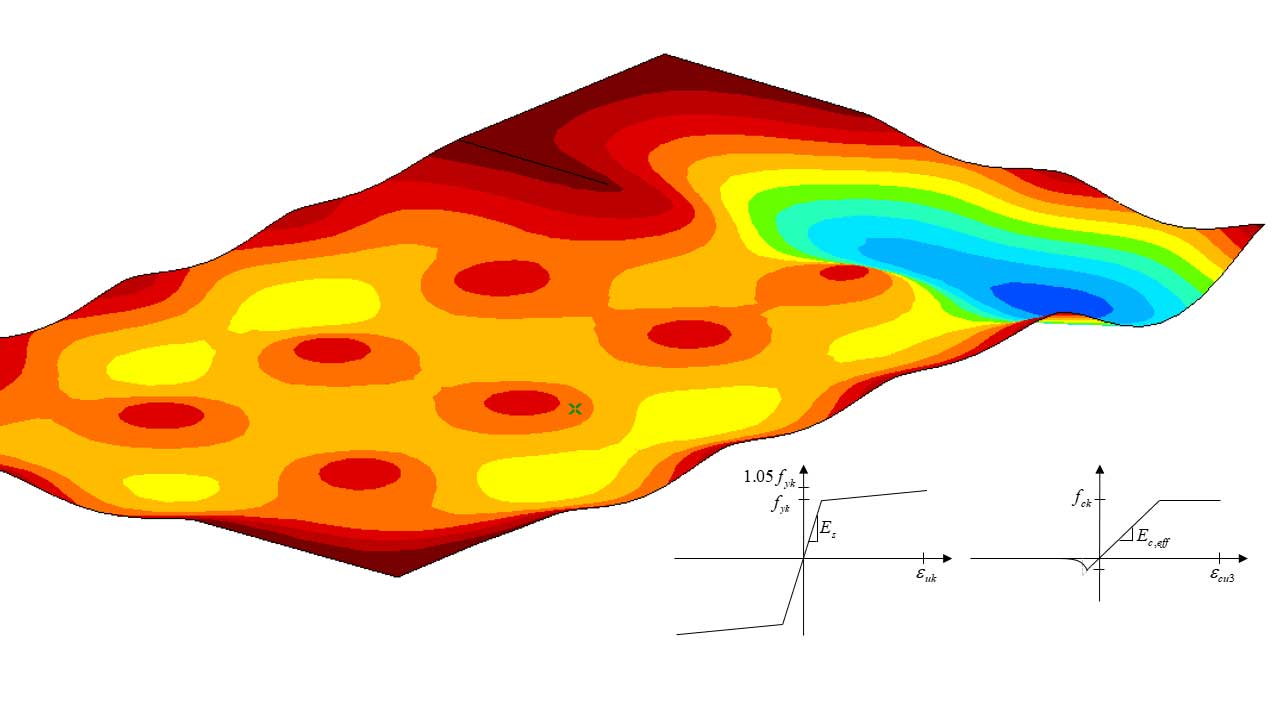
If linear static analysis is performed, the deflections are calculated based on linear theory, however, reinforced concrete surfaces behave nonlinearly mainly due to cracking. In AxisVM, deformations of reinforced concrete surfaces can be determined more accurately using nonlinear static analysis that considers cracking and actual reinforcement in the element. Internal forces compatible with the corresponding strains are calculated by numerical integration of fiber stresses at the Gauss integration points based on εx, εy, εxy membrane strains and κx, κy, κxy curvatures.
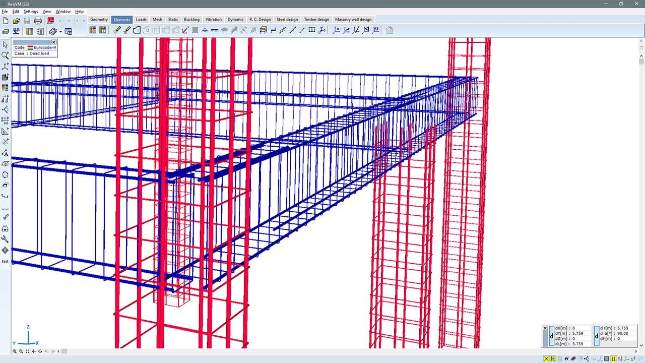
ACTUAL REINFORCEMENT IN 3D VIEW
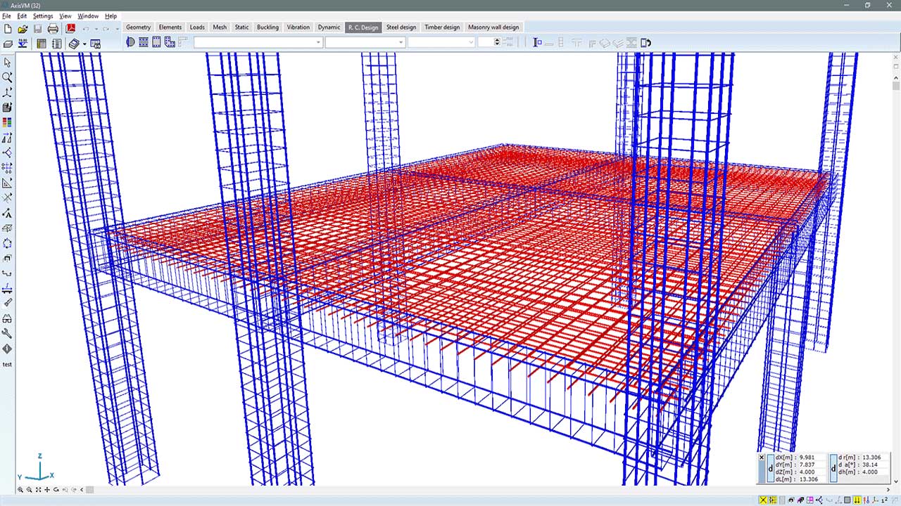
The actual reinforcement of surfaces can be displayed in a rendered view, helping to control the design and identify modeling errors.
RC2 MODULE
The RC2 module provides for the design and verification of reinforced concrete beams and columns corresponding to the ultimate (ULS) and serviceability limit states (SLS). In the case of columns, ULS verification can be performed for biaxial bending with or without axial force considering buckling phenomenon, and for shear forces and torsional moments considering constant or variable stirrup distance. For beams, determination of the bending reinforcement is based on ULS or SLS requirements. Full verification of the actual bending and shear reinforcement and detailed documentation of the design calculations are available. For both columns and beams, AxisVM supports capacity design that comes to the fore in cases of seismic design of dissipative structures.
Documentation sample (reinforced concrete beam) >>
Documentation sample (column reinforcement – shear & torsion check) >>
Documentation sample (column reinforcement – eccentricity) >>
Requirements / recommendations
- at least an NL1 configuration is required for the analysis of nonlinear deflection of ribs and beams
- the SE1 module is required for capacity design
DESIGN CODES
Eurocode2
EN 1992-1-1
Eurocode4
EN 1994-1-1
Swiss standard
SIA 262
SIA 264
Italian standard
NTC
CHARACTERISTICS
- shifting bending moment diagram for beams
- verification of composite columns
- verification of compliance with design code detailing rules
flexible and user-friendl - definition of design parameters and rebars
- calculation of required reinforcement from specified limiting crack width
- capacity design for beams and columns
- shear and torsion verification for beams and columns
- detailed documentation of design calculations
DETAILS
ACTUAL REINFORCEMENT
The actual reinforcement of columns and beams can be shown in rendered view. This reinforcement is taken into account by the calculation of crack width for beams and by the calculation of stiffness in nonlinear analysis for both beams and columns considering the effect of cracking, creep and shrinkage of concrete.
COMPOSITE COLUMNS
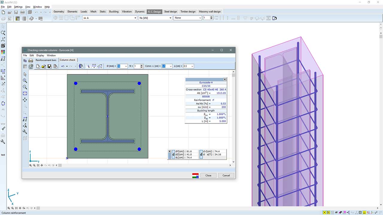
ULS verification of composite columns for biaxial bending, with or without axial force considering the buckling phenomenon, can be performed according to Eurocode and SIA standards. Concrete-filled tube and rectangular hollow sections, with or without encased steel profile, and circular and rectangular concrete sections with encased steel profiles are supported.
NONLINEAR DEFLECTION
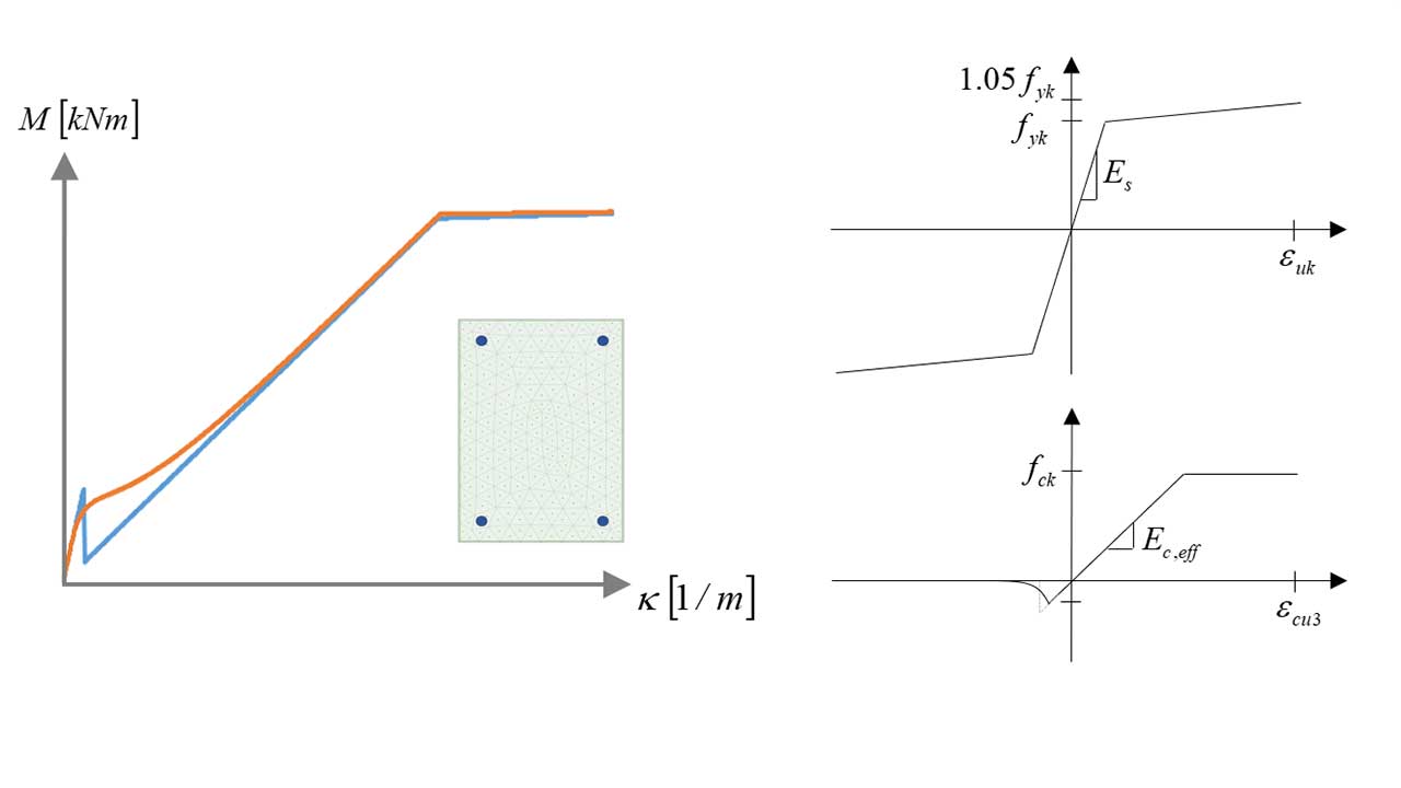
If actual reinforcement is assigned to reinforced concrete column or beam elements in nonlinear static analysis then the actual reinforcement, concrete parameters, and steel and concrete nonlinear material behaviour (including the cracking of the section) can be taken into account. Internal forces compatible with strains are calculated by numerical integration of fiber stresses based on ε normal strains, κy and κz curvatures. The consideration of creep and shrinkage in nonlinear static analysis is supported. In the case of shrinkage, two additional κy and κz curvatures are calculated based on the given shrinkage strain, the arrangement, and amount of reinforcement.
CAPACITY DESIGN
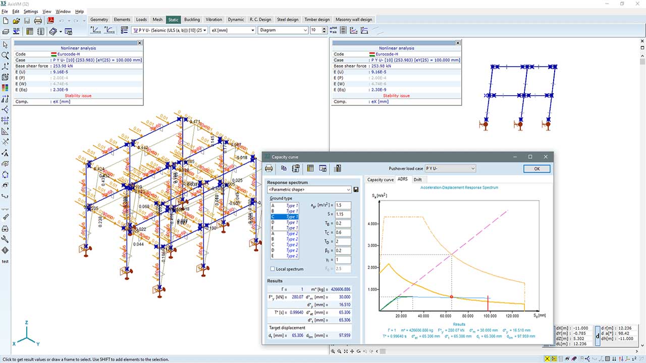
In the case of dissipative structures with DCM or DCH ductility class, in order to avoid shear failure, the design values of shear forces are determined in accordance with the capacity design rule. Details and actual reinforcement of plastic hinges may be specified by the user. In the process of verification, detailing rules set by design codes are taken into account.
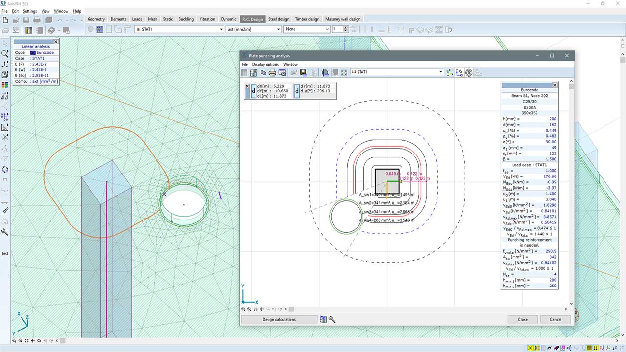
RC3 MODULE
It is often the case that reinforced concrete slabs are directly supported by columns or walls. The resistance of the slab needs to be verified against punching shear failure around those areas where the slab is subjected to high local forces. With the RC3 module, punching shear verification of slabs can be performed at columns, wall corners and wall ends. The punching shear force can be calculated by the integration of shear forces in the slab and the design calculation takes into account openings and soil reaction of foundation slabs within 6d range from a column contour.
Shear design of slabs and shells is available when using the RC3 module. AxisVM calculates the shear resistance of the concrete section without shear reinforcement, the required shear reinforcement (asw), and the maximum shear resistance related to the failure of concrete compression struts.
Documentation sample (plate punching analysis) >>
Requirements / recommendations
- verification and design of reinforced concrete slabs requires configuration 2 or 3 (e.g. NL2S, L3P)
DESIGN CODES
Eurocode2
EN 1992-1-1
Swiss standard
SIA 262
Italian standard
NTC
CHARACTERISTICS
- flexible and user-friendly definition of design parameters
- consideration of soil reaction for foundation slabs
- calculation of required punching reinforcement at each punching perimeter
- calculation of punching force by integration of shear forces in the slab
- automatic determination of the eccentricity of punching force
- detailed documentation of the design calculations
DETAILS
OPENINGS
The RC3 module automatically detects plate edges and openings closer than 6d to the selected column/wall end, and AxisVM calculates the effective part of the punching perimeter with respect to the plate edges and openings considered.
INTEGRATION
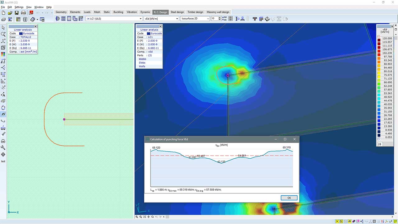
In the case of columns, by default, the punching force is calculated from the difference in axial forces of the connected columns. The calculation of the shear forces in the slab by integration is optional. If a wall end or corner is considered, the punching force is calculated by integration in every case.
The integration of forces allows for the analysis of special situations (e.g. large concentrated forces close to the column contour).
DETAILED DESIGN CALCULATIONS
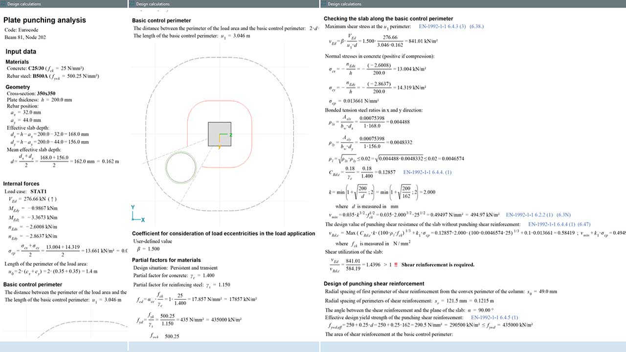
Detailed documentation of the design calculations can be generated and attached to the report by one simple click.
RC4 MODULE
The RC4 module allows for the design and verification of pad and strip footings. Simple plates, stepped, and sloped pad footings with rectangular or circular shapes are supported. The type of strip footings can be simple, stepped, or sloped. The software calculates the required sizes and the settlements. In the case of a rectangular plate and strip footings, the software determines the required bending reinforcement. For rectangular plate footings, the shear reinforcement is also calculated. Analysis of the bearing capacity of the soil, load eccentricity, and of foundation sliding, loss of stability, and uplift are supported. The program can also verify the seismic resistance of the footings according to Annex F of EN 1998-5. The user can specify multi-layered soil profiles and a comprehensive soil database is available to find the required parameters.
Documentation sample (pad footing design) >>
Requirements / recommendations
no requirement
DESIGN CODES
Eurocode2
EN 1992-1-1
Eurocode7
EN 1997-1
Eurocode8
EN 1998-1
EN 1998-5
Italian standard
NTC
Swiss standard
SIA 262
SIA 265
CHARACTERISTICS
- rectangular and circular pad footing
- simple plate, stepped, or sloped footingá
- The wide range of design parameters
- GEO, STR, EQU verifications
- optimization of the area (sizes) of the foundation
- seismic load capacity
- flexible and user-friendly definition of geometry, soil and reinforcement parameters
- calculation of stresses and settlements based on multilayered soil profile
- comprehensive soil database
- detailed documentation of the design calculations
DETAILS
SKEW REINFORCEMENT
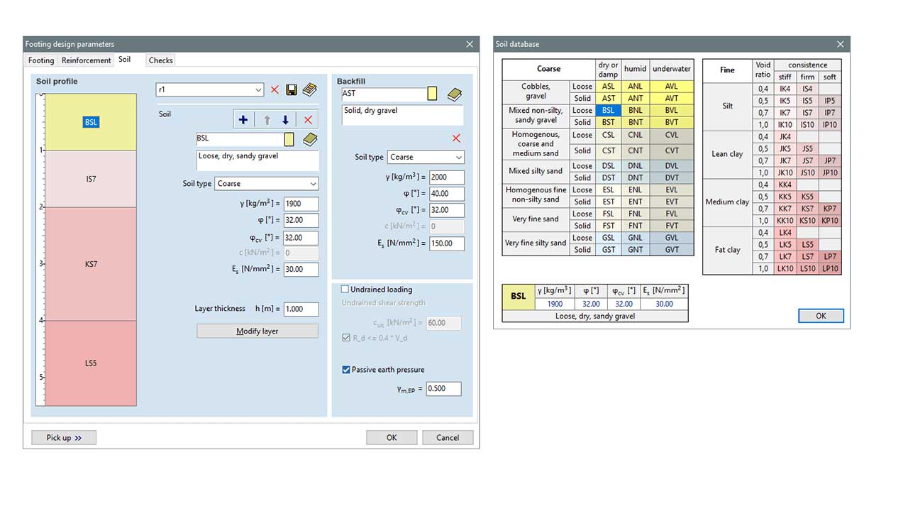
The user can specify the soil profile and the properties of the backfill. Among others, the position of the top surface relative to the ground level, mass density, internal angle of friction, Young’s modulus, and cohesion can be specified for each layer. A comprehensive soil database assists in finding the required parameters. The soil profile can be saved.
CALCULATION OF SETTLEMENT
The predicted settlement at a given depth is calculated as the sum of the changes in the thickness of the sublayers above that level. The stress calculation is based on formulae derived for a homogeneous half-space.
RESULT DISPLAY
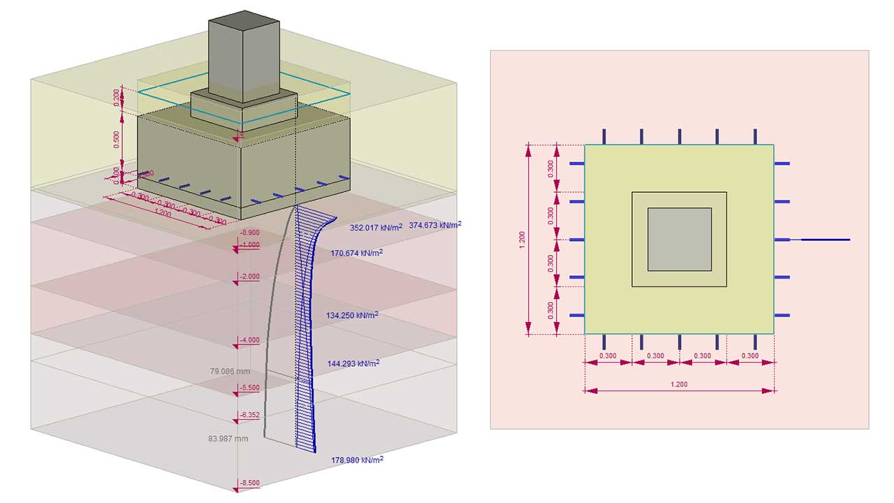
The designed foundation is automatically displayed with soil layers, punching circles, and dimension lines. It gives a detailed overview of the results of the design and the 3D model can be zoomed in and out, shifted and rotated. The drawing can be saved in the report.
DETAILED DESIGN CALCULATIONS
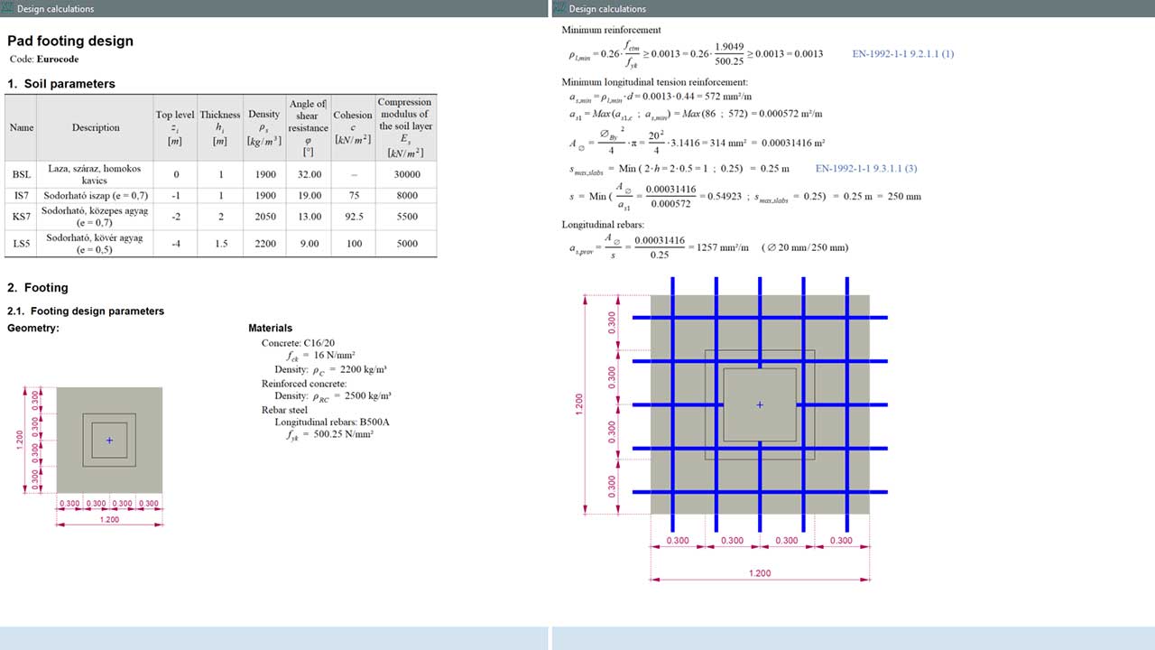
Detailed documentation of the design calculations can be generated and attached to the report by one simple click.
RC5 MODULE
Reinforced concrete walls and cores are generally subjected to axial and shear forces and bending and torsional moments due to their function, namely providing the lateral stiffness of the whole building and carrying the gravitational loads on the slabs. Using the RC5 module, reinforcement can be assigned to reinforced cores and walls and the design of cores/walls can be subjected to bending moments and shear and axial forces. Reinforcement can be assigned to virtual beams or virtual strips. Virtual beams can be used to design reinforced concrete cores while wall- ends and wall segments can be designed with the help of virtual strips considering possible buckling failures of the wall between floors. Using stories, more economical and efficient reinforcement can be assigned to the virtual beam that follows the change in the internal forces.
Requirements / recommendations
- design of reinforced concrete walls and cores requires configuration 2 or 3 (e.g. L2S, NL3P)
DESIGN CODES
Eurocode2
EN 1992-1-1
Swiss standard
SIA 262
Italian standard
NTC
CHARACTERISTICS
- calculation of overall utilization of the core
- verification and design for shear forces
- verification of compliance with design code detailing rules
- flexible and user-friendly definition of design parameters and rebars
- 3D graphical display of actual reinforcement in rendered view
DETAILS
ACTUAL REINFORCEMENT
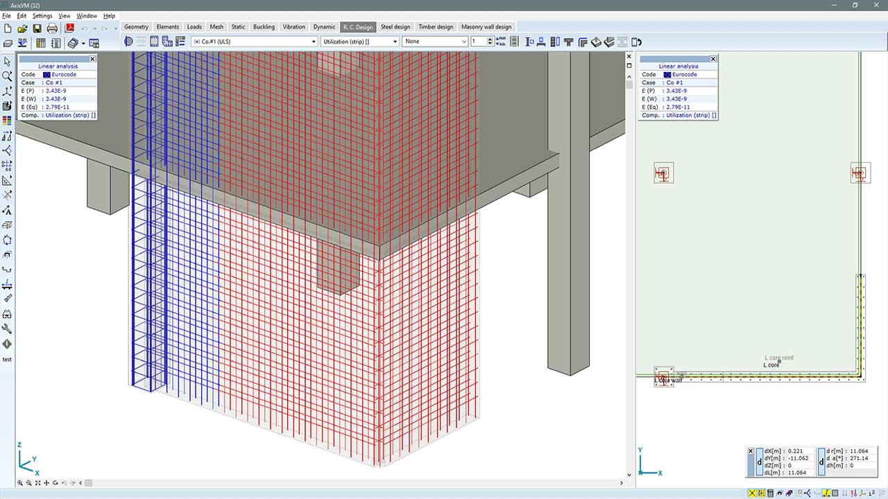
The actual reinforcement of walls and cores can be displayed in a rendered view, helping control the design and identify modeling errors.
OVERALL UTILIZATION
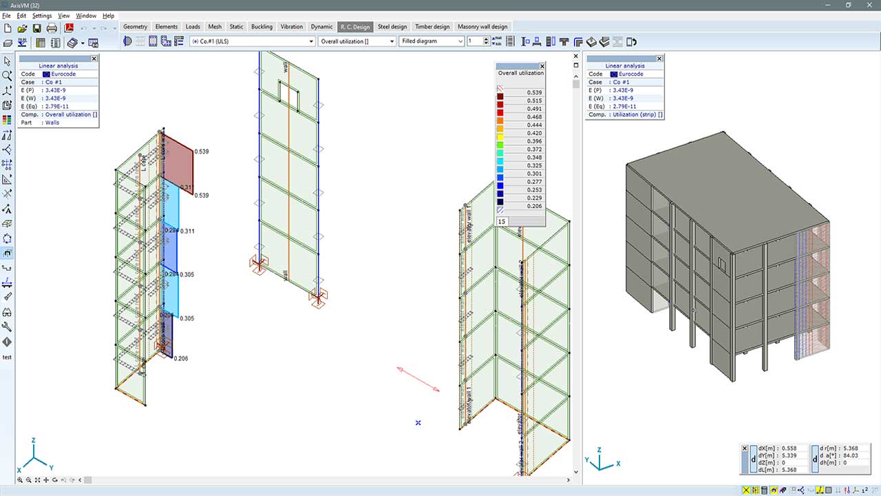
The design results of reinforced concrete cores calculated with virtual beams and the design results of wall ends/segments calculated with virtual strips can be summed. It may be necessary, since the Nx-My-Mz strength interaction diagram of cores is generated without consideration for the loss of stability of compressed wall ends and inner wall segments. The program supports the use of various summation rules.
SHEAR VERIFICATION FOR WALLS
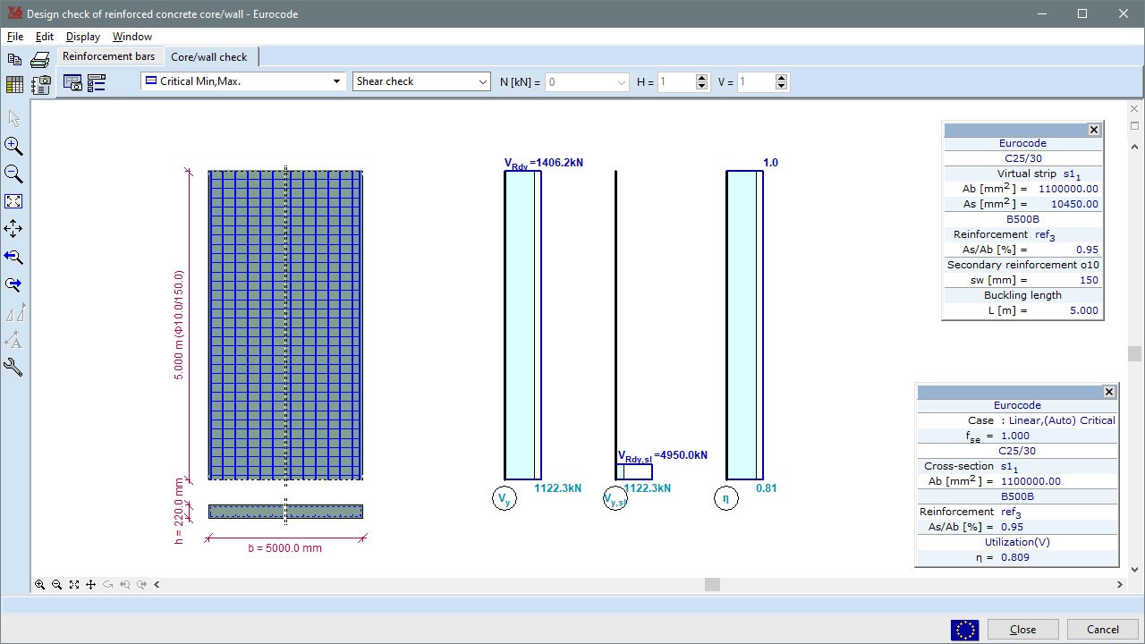
AxisVM supports in plane shear verification of wall segments with the help of virtual strips. Shear resistance of the rectangular wall section is calculated based on the amount of horizontal reinforcement in the wall. The check of sliding shear at the bottom section is also incorporated. The results are shown graphically and in result tables. Furthermore, shear utilization of walls is also available as result component in the software.
RC6 MODULE
In serviceability limit state design or in the case of pre/post-tensioned structural elements, the compression stresses in the concrete need to be limited. Furthermore, the stresses and strains in the concrete or in the rebars need to be known in many cases (e.g. crack width calculation, fatigue analysis). With the RC6 module, stress-strain analysis of reinforced concrete beams and columns can be performed considering bending moments (My, Mz) and axial force (Nx) obtained from a static analysis or given by the user. The analysis considers cracking of the section and nonlinear behaviour of the concrete and steel.
Requirements / recommendations
- the RC2 module is required
DESIGN CODES
Eurocode2
EN 1992-1-1
Swiss standard
SIA 262
Italian standard
NTC
CHARACTERISTICS
- stress-strain analysis with nonlinear material models for concrete and steel
- selection of any cross-section along the member with a track bar, making the analysis fast and easy
- analysis can be performed for internal forces obtained from a load case, load combination, envelope or critical combinations, or direct user input
- results are presented in tables and drawings that can be saved in the design report
DETAILS
INTEGRATION
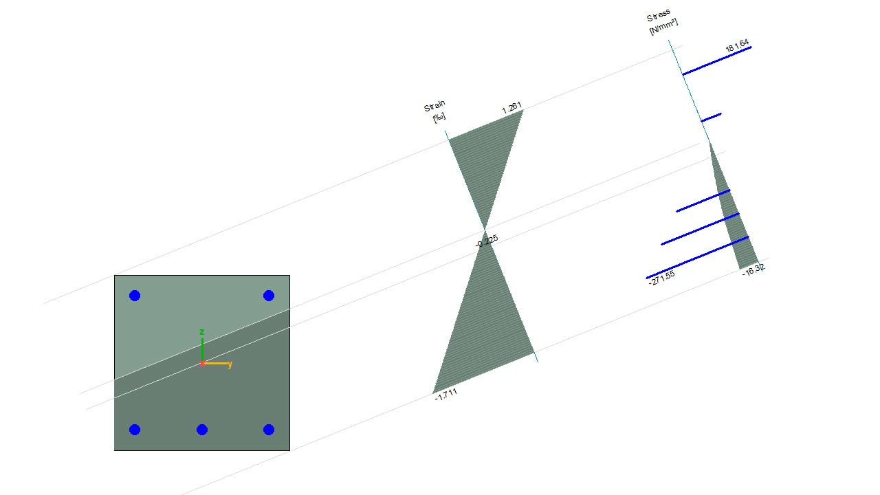
Internal forces compatible with strains are determined by numerical integration of fiber stresses based on ε normal strain, κy and κz curvatures. The materials and the considered nonlinear materials model for the concrete can be specified by the user.
ITERATION
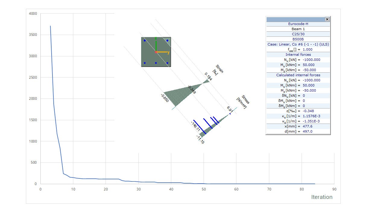
The aim of the stress-strain analysis is to find ε normal strain, κy and κz curvatures for the given internal forces. Since this problem is nonlinear and not continuous, a heuristic algorithm is invoked to find the equilibrium.
PS1 MODULE
Tendons can be assigned to a continuous selection of beam, rib, or domain elements. The software determines the stress distribution in tendons immediately after anchoring and identifies the time dependent losses. AxisVM calculates the equivalent loads based on the given tensioning process by which the effect of tensioning can be considered in static analysis. Complex, spatial tendon geometry can be defined with a multistep post tensioning process where the intensity and the direction of tensioning can vary.
Requirements / recommendations
- verification/design of reinforced concrete beam structure requires configuration 1 or 3 (e.g. L1S, NL3P)
- verification/design of reinforced concrete slabs requires configuration 2 or 3 (e.g. L2S, NL3P)
DESIGN CODES
Eurocode2
EN 1992-1-1
CHARACTERISTICS
- 3D graphical display of tendons in a rendered view
- vertical or inclined tendon coordinate system
- multi-step post tensioning process
- calculation of tensioning losses along the member
- tendon trajectory tables can be generated
- detailed documentation of the tensioning process
DETAILS
TENSIONING PROCESS
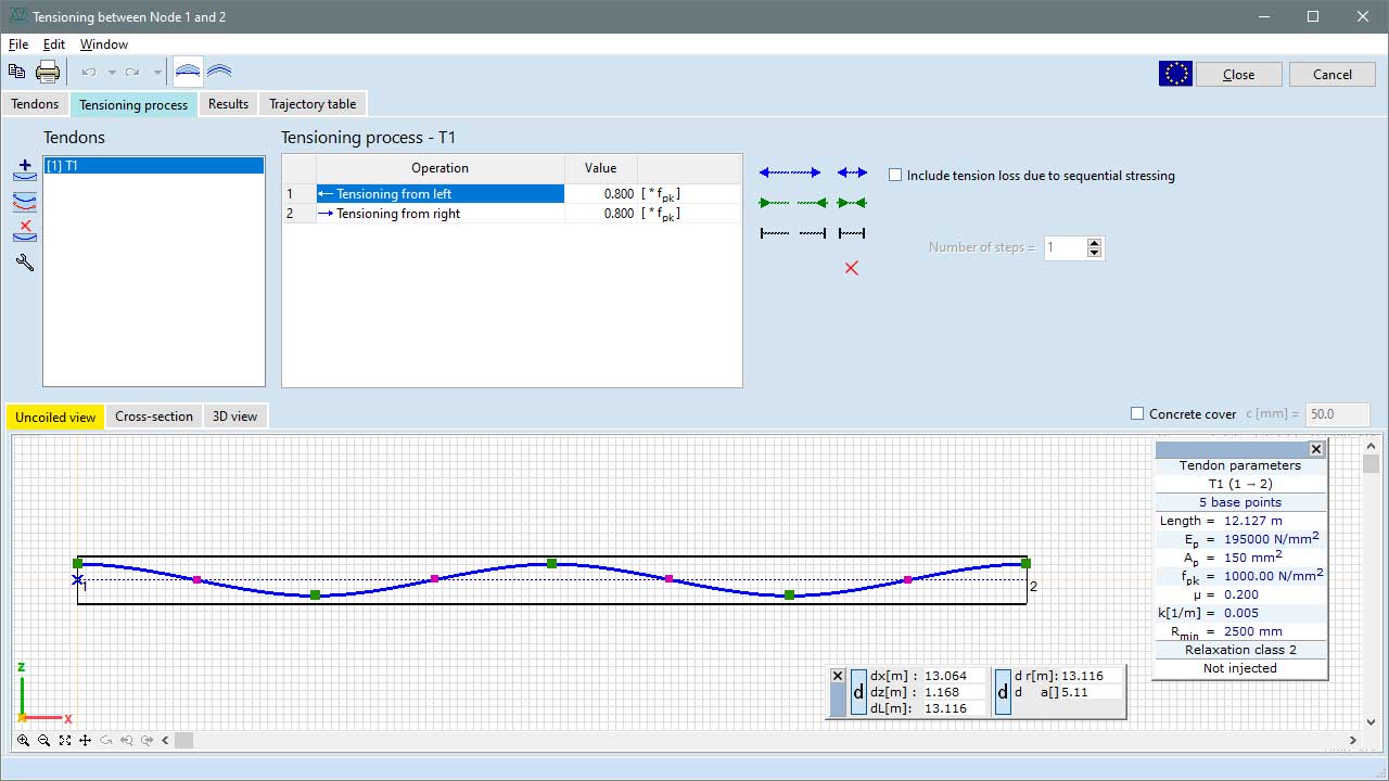
If more than one cable is related to a structural element, then these cables can be stressed at different times. As a result, stress loss arises in the previously anchored tensioned cables. In the PS1 module, this phenomenon can be taken into account.
TENDON COORDINATE SYSTEM IN DOMAIN
In order to facilitate the definition of tendons in domains, the trajectory coordinate system or the local coordinate system of the domain can be selected. Each tendon has its own coordinate system.
TENDONS IN RENDERED VIEW
The tendons in beams, ribs, and domains can be shown in a rendered view, helping control the design and identify modeling errors.
RC8-B MODULE
The fire design of reinforced concrete columns and beams can be performed in the software according to the guidelines of Eurocode 2, SIA 262 and NTC design codes if the RC8-B module is available. The software analyses the temperature distribution inside the cross-section, calculates the temperature of longitudinal and shear reinforcement , as well as takes into account the spalling of damaged concrete layers.
Requirements / recommendations
- fire design of reinforced concrete members is based on the conventional reinforced concrete design, thus RC2 module is a prerequisite to the use of the RC8-B module
DESIGN CODES
Eurocode1
EN 1991-1-2
Eurocode2
EN 1992-1-1
EN 1992-1-2
Swiss standard
SIA 261
SIA 262
Italian standard
NTC
CHARACTERISTICS
- temperature distribution analysis
- temperature dependent material properties for steel and concrete
- consideration of spalling of damaged concrete layers
- design and verification of bending and shear reinforcement
- detailed documentation of the design calculations
DETAILS
TEMPERATURE DISTRIBUTION ANALYSIS
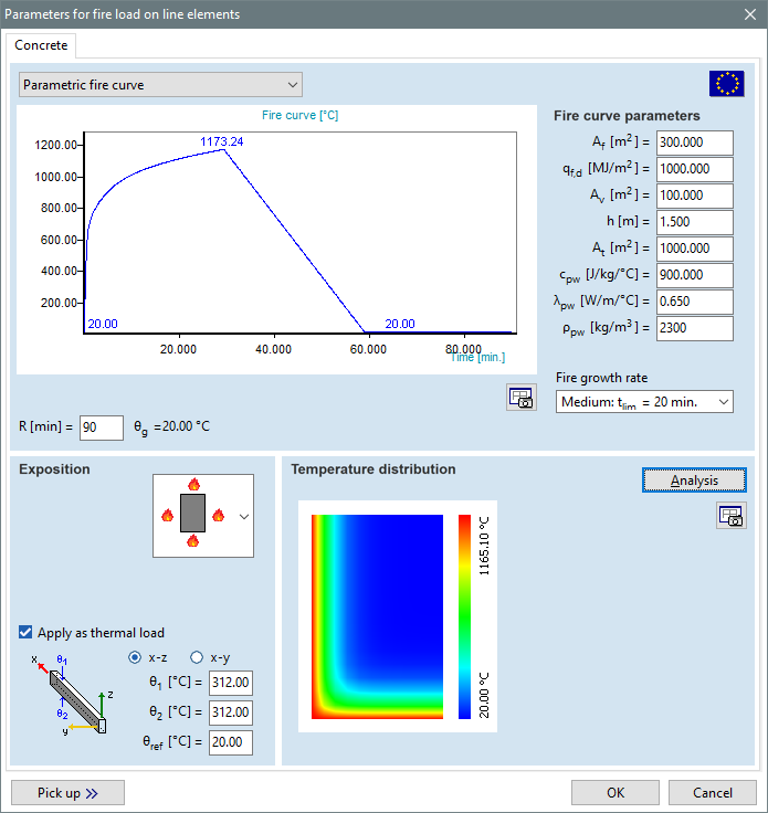
The software solves the 2D heat transfer problem with the help of finite difference method. The temperature dependent parameters are calculated according to EN 1992-1-2. A colour scale in the figure helps to identify warmer and cooler areas. If you move the cursor over the figure, the software displays a small pop-up window showing the calculated temperature at the position of the cursor.
FIRE DESIGN - REINFORCED CONCRETE COLUMNS
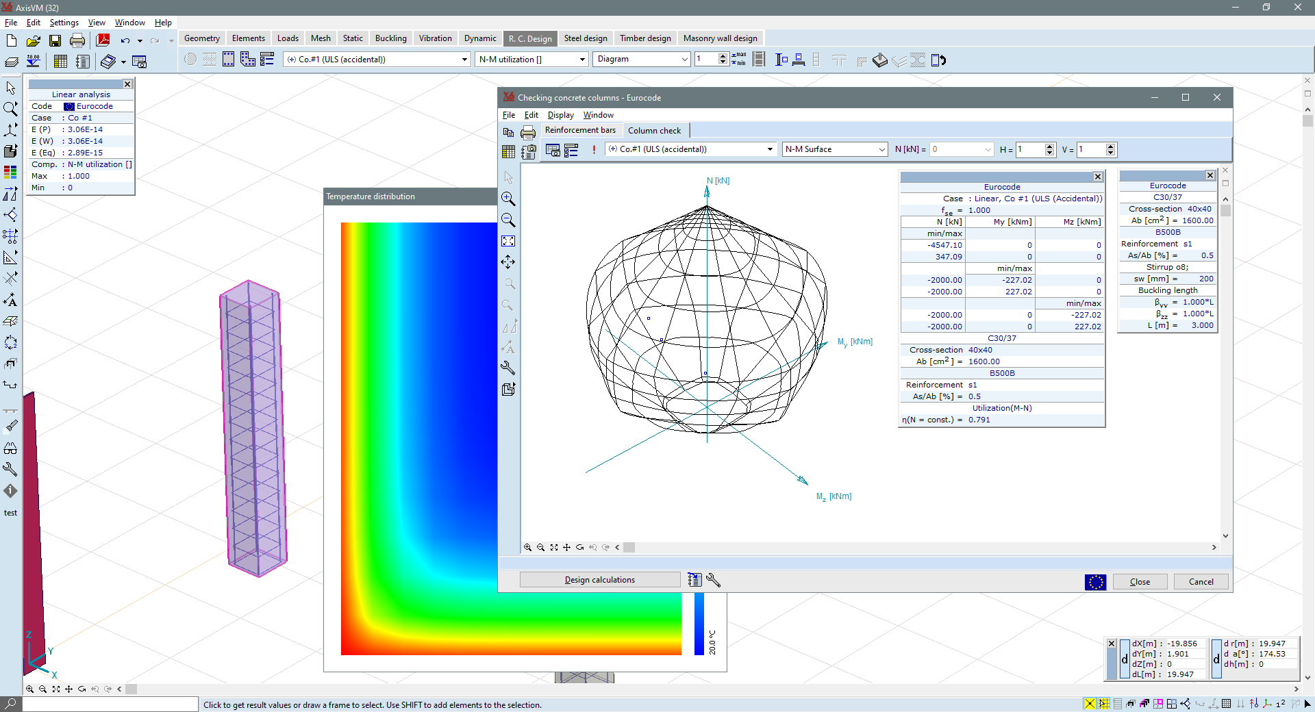
The recommendations and guidelines of Annex B of EN 1992-1-2 are taken into consideration in the calculation of Nx-My-Mz interaction surface.
The eccentricities are calculated similarly to normal temperature design, however, reduced sectional resistance and stiffness are considered according to the damaged outer concrete layers and the change in the properties of concrete and steel on elevated temperature. Shear and torsional performance are also evaluated considering reduced cross-section and reduced material properties.
FIRE DESIGN - REINFORCED CONCRETE BEAMS
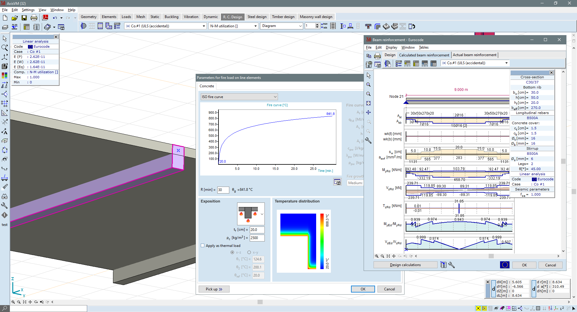
The recommendations and guidelines of Annex B of EN 1992-1-2 are taken into consideration in the course of the verification or design of longitudinal reinforcement. The modified strength of each rebar is taken into account based on the temperature of the reinforcement. Shear and torsional performance are also evaluated considering reduced cross-section and reduced material properties.
RC8-S MODULE
The fire design of reinforced concrete surfaces can be performed according to the guidelines of Eurocode 2, SIA 262, and NTC design codes if the RC8-S module is available. Once the fire design parameters are assigned to the concrete domains, the software analyses the temperature distribution inside the cross-section and the design takes into account the temperature of the longitudinal reinforcement as well as the spalling of the damaged concrete layers.
Requirements / recommendations
the fire design of reinforced concrete surfaces is based on the conventional reinforced concrete design, thus the RC1 module is a prerequisite to the use of the RC8-S module
DESIGN CODES
Eurocode1
EN 1991-1-1
Eurocode2
EN 1992-1-1
EN 1992-1-2
Swiss standard
SIA 261
SIA 262
Italian standard
NTC
CHARACTERISTICS
- temperature distribution analysis
- temperature dependent material properties for steel and concrete
- consideration of spalling of damaged concrete layers
- design and verification of longitudinal reinforcement in fire design situations
DETAILS
TEMPERATURE DISTRIBUTION ANALYSIS
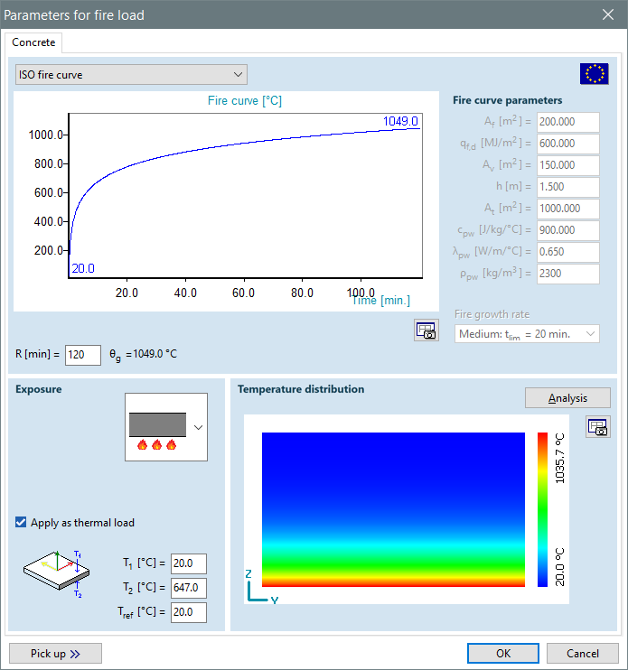
The software solves the 1D heat transfer problem using a finite difference method. The temperature dependent parameters are calculated according to EN 1992-1-2. A colour scale in the figure helps to identify warmer and cooler areas. If the cursor is moved over the figure, the software displays a pop-up window showing the temperature determined at the location specified by the cursor.
DESIGN OF LONGITUDINAL REINFORCEMENT IN FIRE DESIGN SITUATIONS
The software performs the calculation of the required reinforcement and the verification of the actual reinforcement according to the simplified methods presented in Annex B of EN 1992-1-2 standard. The reduced cross-section due to spalling, as well as the modified strength of each rebar based on the steel temperature, are considered in the analysis.