TIMBER STRUCTURES
The modules developed for timber structures encompass a broad range of the design practice. With the help of these modules, simple and complex space frame structures can be analysed, cross-sections can be optimised according to various criteria, and the reliability of these structure under fire can be ensured.
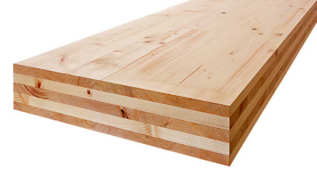
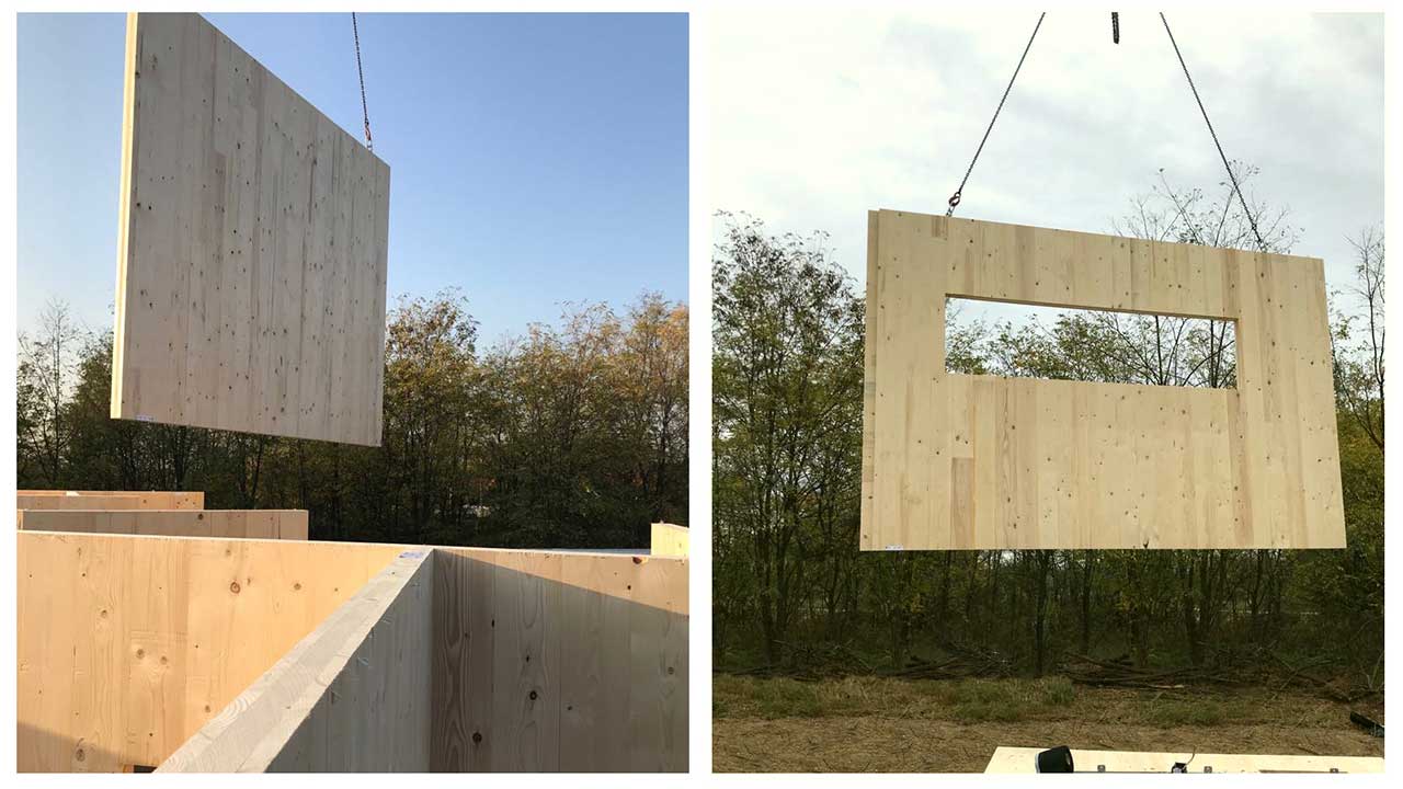
Nowadays, the use of cross-laminated wood panel structures – CLT (XLAM) is expanding, due to their advantageous building physics, strength properties, and almost unlimited uses. Satisfying market requirements, the unique XLM module provides an appropriate theoretical and computing background for the design of these innovative structures.

TD1 MODULE
Design of timber elements
TD8 MODULE
Fire design of timber elements
TD9 MODULE
Cross-section optimization fot timber elemente
XLM MODULE
Modeling of CLT (XLAM) panels + databasis
TD1 MODULE
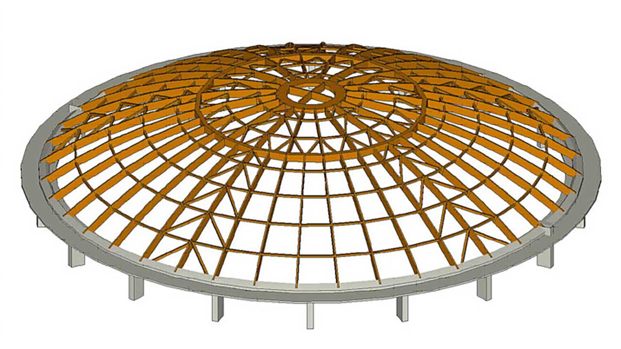
From the simplest to the most complex timber space frames, many types of structures can be analysed with this module. The analysis is performed on design members that consist of one or more finite elements (beams or ribs) satisfying the requirements of a continuous element. The verification of design members includes the examination of the interaction of internal forces, while the displacement of the elements can be verified according to various criteria. The utilization results and the computed design parameters can be visualized and detailed reports of the design process can be compiled.
Documentation sample (timber member design) >>
Requirements / recommendations
no requirements
TD8 (Fire design of timber elements) and TD9 (Cross-section optimization for timber elements) modules are recommended as supplementary modules for a comprehensive design.
DESIGN CODES
Eurocode5
EN 1995-1-1
Swiss standard
SIA 265
Italian standard
NTC
CHARACTERISTICS
- variable cross-sections, curved beams
- interaction verifications of internal forces according to the
- the verification of the support zones, joints, holes are not included in the verification
CROSS-SECTIONS
rectangular (solid timber, glued laminated timber (GLULAM), laminated veneer lumber (LVL), or other)
round solid timber

DETAILS
TIMBER MATERIAL LIBRARY
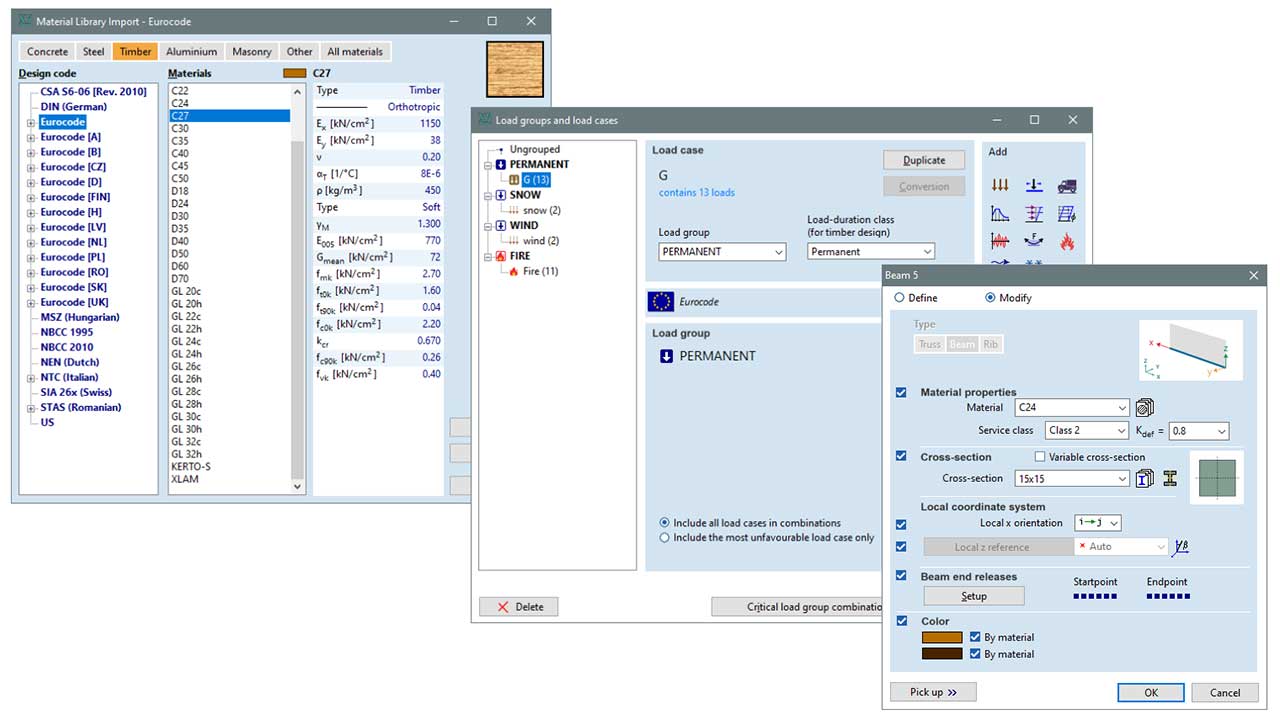
The material library of AxisVM has several predefined timber materials (solid timber, Glulam and LVL products), covering all necessary parameters needed for design. The materials can be edited, or new types of timber products can be added to the database. The service class of the elements are saved with the line elements. The load-duration class is assigned to the load cases.
SPECIAL APPLICATIONS
DESIGN MEMBERS
EVALUATION OF RESULTS
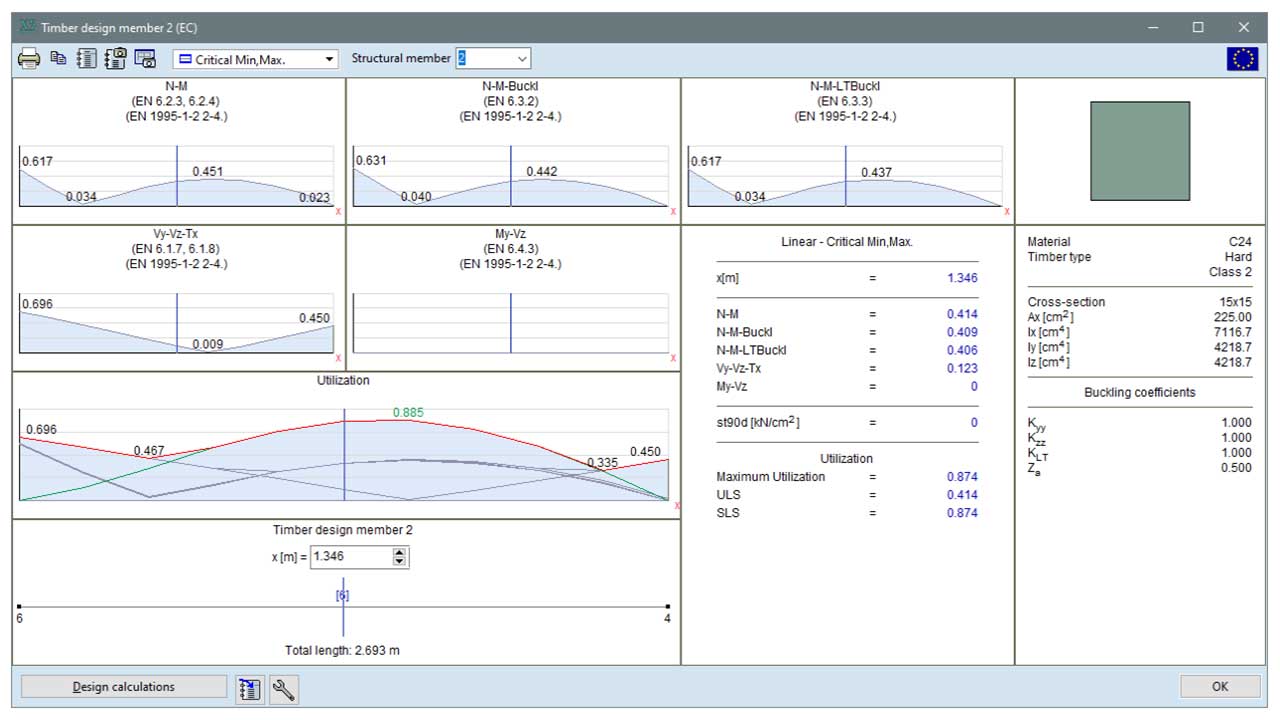
The module supports a variety of tools for evaluating results. The results of each interaction verification and corresponding calculated parameters can be displayed in the model by a diagram. Summary diagrams are available in a separate window. In addition to the critical utilization, the partial results of each interaction verification can be queried, which provides information about the critical load case or failure type of the member. Detailed design calculations can be requested for the complete verification, which is automatically updated when the model is changed.
DISPLACEMENTS
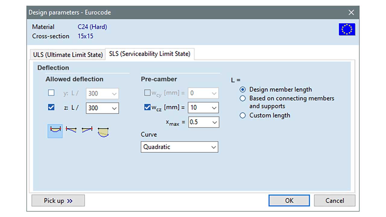
Deflection verification can be performed in two main directions (local y and z axis). The reference point of the deflection can be relative to the endpoints of the elements or the actual displacement. When necessary, pre-camber can also be taken into account by specifying a linear or second-order curve as an initial shape.
TD8 MODULE
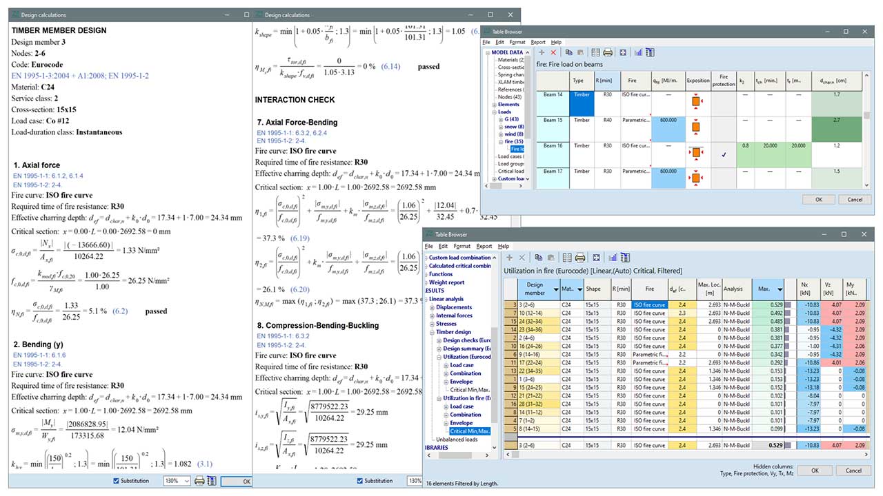
With the help of this module, the reliability of timber elements under fire can be analysed. The analysis lays on the “conventional” verification (see TD1 module) performed at normal temperature but complements it with fire specific verifications. The fire effect is represented by the fire curve specifying the gas temperature in the fire compartment as a function of time. ISO standard or parametric fire curves can be chosen. The module uses the reduced cross-section method when verifying the elements.
Requirements / recommendations
the basic TD1 module is a prerequisite to use TD8
the TD9 module is a practical add-on module which allows for performing cross-section optimization for combinations containing fire load cases
DESIGN CODES
Eurocode1
EN 199-1-2
Eurocodeé5
EN 1995-1-1
EN 1995-1-2
Italian standard
SIA 261
SIA 265
Swiss standard
NTC
CHARACTERISTICS
- fire load case with specific parameters
- ISO type or parametric fire curve
- cross-sections exposure type and protected or unprotected elements
- automatic charring depth calculation
the module uses member analysis - buckling length coefficients can be set independently for fire design verification
- detailed interaction verification and utilization calculation
- design calculation (TD9 is complemented with the results of fire design
DETAILS
DESIGN MEMBERS
The TD8 module performs the so-called member analysis.
Member analysis is the most popular verification method due to its simplicity. Analysis of a part or whole of the structure usually would require complex nonlinear numerical models and nonlinear static analysis. Following the member analysis, the internal forces of the design members can be calculated with a linear static analysis and the boundary conditions at supports may be assumed to be constant over time.
FIRE LOAD CASE
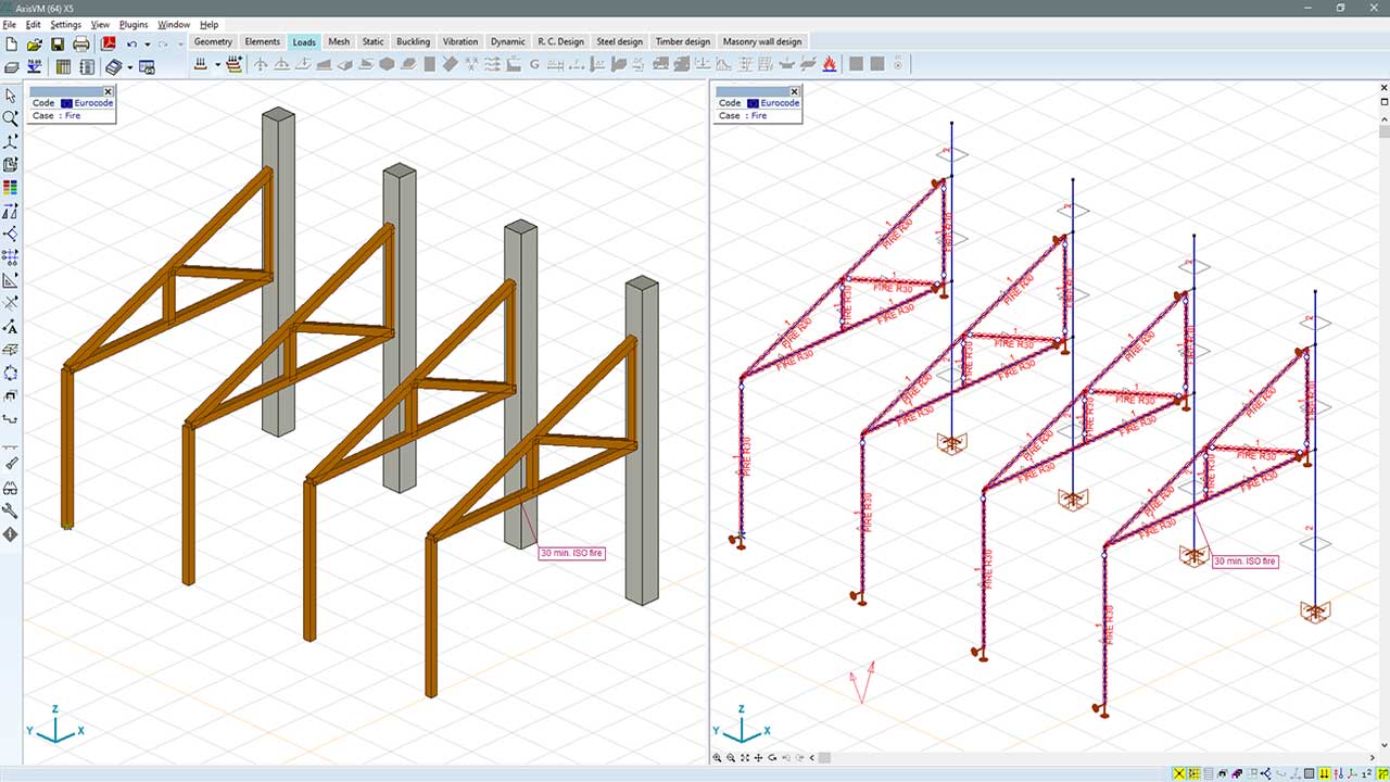
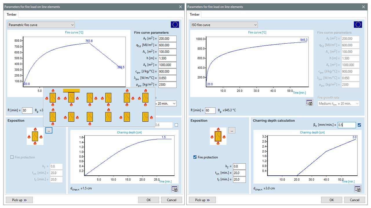
The fire effect is represented by the fire curve specifying the gas temperature in the fire compartment as a function of the time. In the case of timber elements, ISO standard or parametric fire curves can be selected. The charring depth is calculated automatically from the selected fire curve and fire duration time of fire resistance.
Among the above parameters, type of exposure to the elements can also be set. Additionally, the members can be specified as protected or unprotected.
PARAMETERS OF ELEMENTS FOR FIRE DESIGN
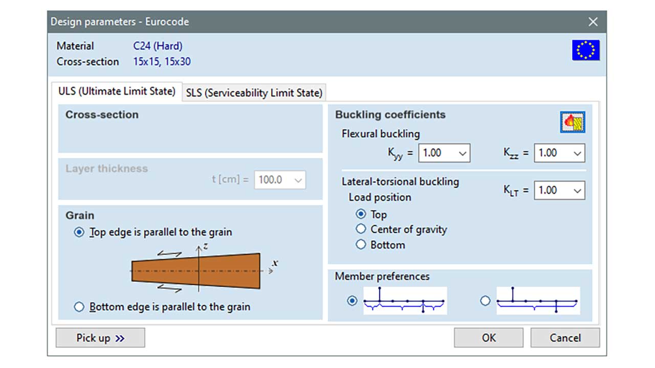
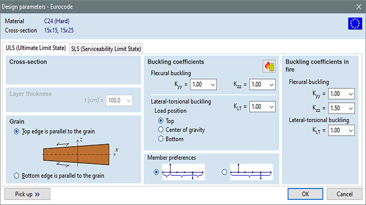
It is possible to define different buckling length coefficients in fire because the deflection of the element is often prevented by other elements that may lose their stiffness or resistance in a shorter period of time. The definition/calculation of buckling length is the same as in the case of normal temperature design.
REDUCED CROSS-SECTION METHOD
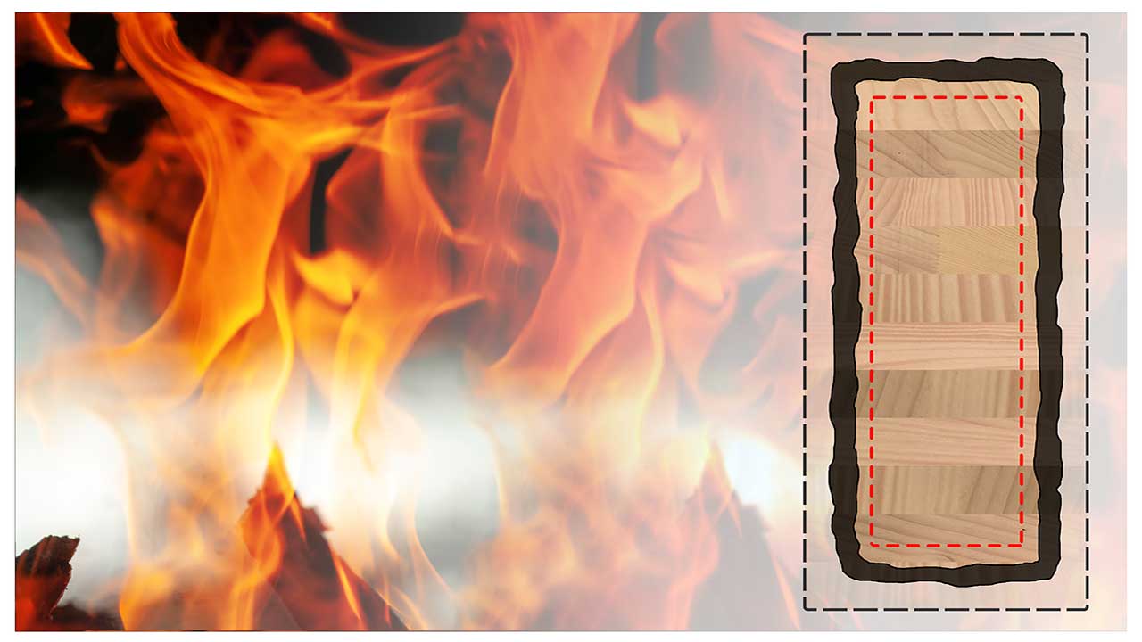
The module implements the reduced cross-section method. As a first step, the so-called effective charring depth is determined using the notional charring depth. Then, the cross-section is reduced with this effective charring depth on the exposed sides. This reduced cross-section is called the effective cross-section.
TD9 MODULE
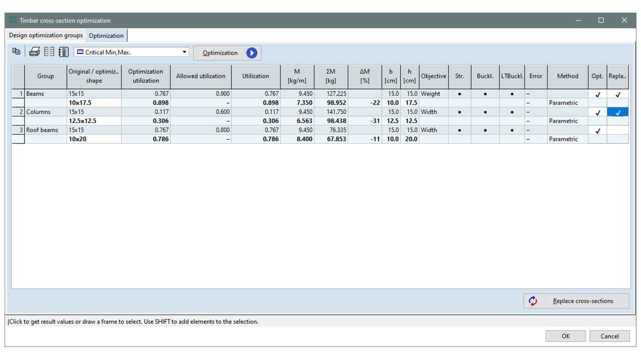
After the design of timber elements in the TD1 module, the structural elements can be made more economical using the cross-section optimization procedure of the TD9 module. Various adjustable criteria control the optimum finding. As the target of the optimization, minimum weight, height, width and maximum allowable utilization can be chosen. The search algorithm is built on a stochastic search method (PSO) which provides a relatively short run time and thorough search of the search space. The parallel algorithm can utilize all the cores of the processor.
Requirements / recommendations
the module requires the use of the TD1 module (Design of timber elements). The TD8 module (Fire design of timber elements) is recommended as an accessory package
this module is a useful complement to the TD1 and TD8 modules
DESIGN CODES
Eurocodeé5
EN 1995-1-1
Italian standard
SIA 265
Swiss standard
NTC
CHARACTERISTICS
- the objective of the optimization can be minimum weight, height, width and maximum allowable utilization
- optimization verification may be adjustable
- the set of candidate cross-sections can be taken from the cross-sections of the model or the sections library or the geometries (shapes) can be defined parametrically
- the implemented search evolutionary algorithm is based on the so-called Particle Swarm Optimization (PSO)
- the parameters of the optimization can be freely set
- parallel search processes use all processor cores, thus going through the search space faster
CROSS-SECTIONS
rectangular
rounded rectangular
circular shape
! variable cross-sections cannot be optimized
DETAILS
OPTIMIZATION PARAMETERS
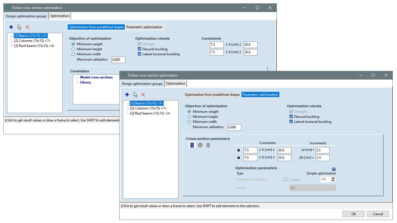
As a first step, the timber design members are classified into optimization groups, on which the optimization can be performed setting various criteria. The goal of the optimization can be minimum weight, height width and maximum allowable utilization. The set of design checks considered may also adjustable. Candidate cross-sections can be selected from a set of predefined sections or can be defined by parameters.
PSO – PARTICAL SWARM OPTIMIZATION
The module uses the so-called Particle Swarm Optimization (PSO), a stochastic computational method for finding the optimum. It is an evolutionary algorithm developed in the 1990s. The PSO process runs for a given number of iterations, and due to its stochastic nature, can find multiple local optimums. The number of iterations is determined by the program trying to balance running time and the fullest possible mapping of the search space. Moreover, if the algorithm finds no changes in the result after a long period, it assumes that it is the global optimum and quits.
PARALLEL ALGORITHM
In multi-threaded mode, the search space is partitioned among the threads, providing a thorough search and fast convergence. The parallel algorithm can be particularly useful with larger structures that consider a significant number of load cases, or an extensive set of combinations of parameters.
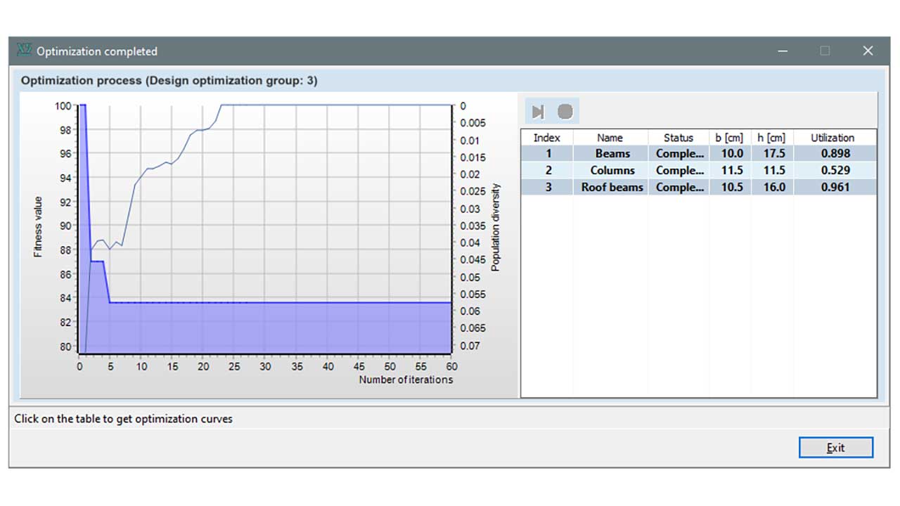
During the calculation, the progress curve provides information about the state of the search and the number of iterations performed.
OPTIMIZATION RESULTS
A summary window provides detailed information about the results of the optimization and the cross-section found by the search criteria. Based on the results of the optimization, the user can decide whether to replace individual sections or to reject suggestions. The modified cross-sections are automatically updated in the model, thus a control static analysis can be performed immediately (changes in stiffness of the elements may induce significant changes in the internal forces depending on the model).
XLM MODULE
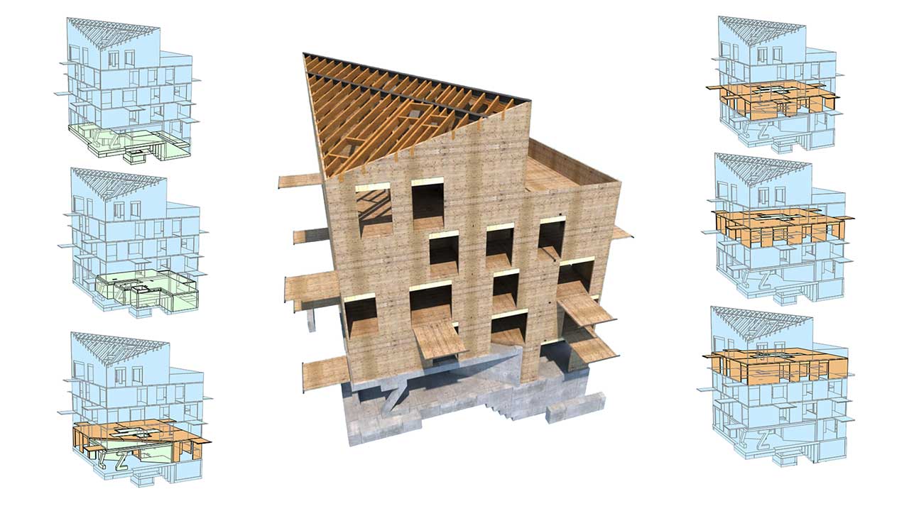
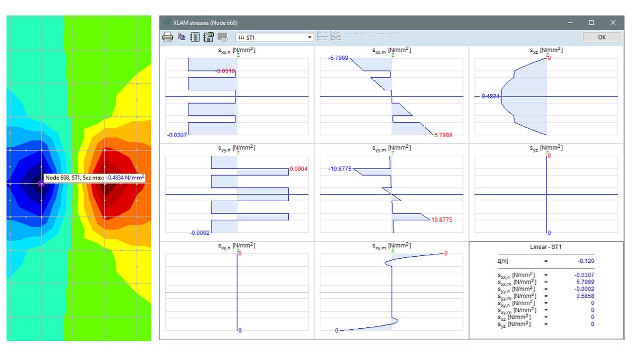
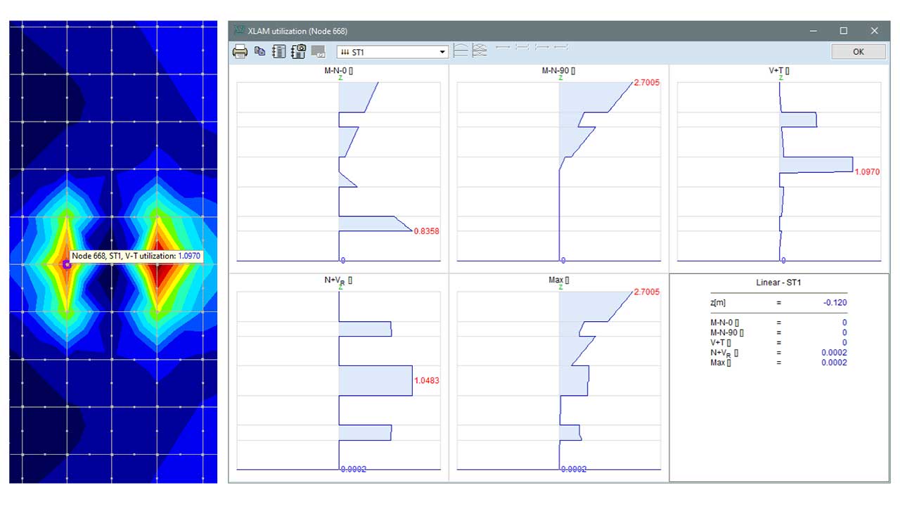
The XLM module allows for the design and verification of structures built from cross-laminated-timber – CLT (XLAM) – panels (walls, slabs, other surface elements). The unique calculation method used is implemented through a complex computational algorithm based on pure mechanics of composite shells. The program offers a number of options for evaluating the results of the CLT panels, displaying the stress distribution of each layer and utilization results, which creates an ideal working environment for optimal design. The module is accompanied by a detailed CLT material database, which includes data on the most commonly used CLT products.
Learn more: CLT/XLAM design guide >>
DESIGN CODES
The module is based on the principles of EN 1995-1-1, but corrects its deficiencies using recommendations of the international literature, providing an improved design procedure
CHARACTERISTICS
- the applied method is based on shell theory, which is suitable for the modelling of arbitrarily shaped domains
- precise calculation of the shear correction factor
- display of stress components in all layers of the cross-section
- maximum and partial utilization results
- unique CLT (CLAM) material database
- the module is accompanied by a detailed manual describing the theoretical background of the applied calculation method
DETAILS
INDIVIDUAL DEVELOPMENT
The unique module developed for AxisVM augments the design procedures of Eurocode 5 for this type of construction. The implementation follows the industry standard practices of composite materials’ mechanics (references in the dedicated theory guide). The attached CLT manual includes a summary of the basic mechanical knowledge required for CLT (XLAM) composite structures and details of the implemented algorithm and verification examples.
SHELL THEORY BASED METHOD
XLAM (CLT) MATERIAL DATABASE
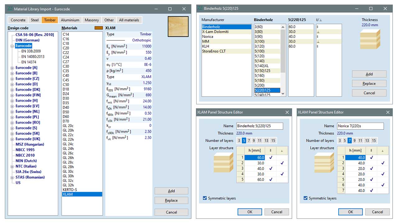
The material database of the module includes the construction parameters of frequently used CLT products (thickness, layer structure, fibre direction), and typical strength values, which are essential for the design of CLT elements. This database can be of a great help, even in the pre-design process, since in most cases it is difficult to obtain all CLT material characteristics required for the modelling.
STRESS COMPONENTS
VARIOUS UTILIZATION COMPONENTS
FURTHER DEVELOPMENTS
The proliferation of CLT panel construction and the dynamic development of manufacturing capabilities pose a significant challenge for structural engineers. Their economical designs are no longer possible without a reliable finite element software background. The XLM module of AxisVM provides an efficient basis for this, and the strong theoretical background offers further development opportunities.

